Map
The Map model tree group contains the following elements of an open-pit mine:
-
Mine nodes
-
Mine arcs
-
Zones
-
Mine areas
-
Mine segments
-
Layout layers
Mine node
Mine node - an element of the mine transport network graph, which corresponds to one point in three-dimensional space.

The mine node is characterized by the following parameters:
-
Unique Identifier
-
X-, Y- and Z-coordinates
Mine arc
Mine arc - an element of the transport network graph that connects two mine nodes.
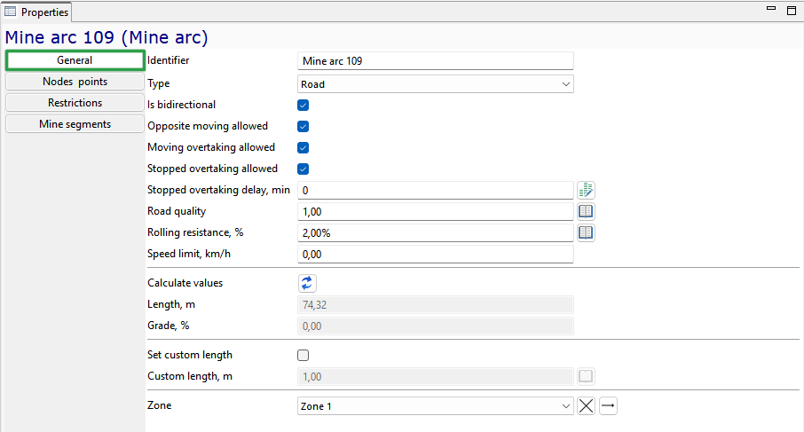
The mine arc is characterized by the following parameters:
-
Unique Identifier
-
Type — one of the following types: Road (non-rail), Rail or Conveyor
-
Is bidirectional — parameter indicating whether travel along this mine arc is possible in both directions (two-way road)
-
Opposite moving allowed — a parameter specifies whether simultaneous movement in the opposite direction is allowed. If not, the equipment will stop in front of the arc to allow those traveling in the opposite direction to pass
-
Moving overtaking allowed — a parameter specifies whether passing of slower vehicles traveling in the same direction is permitted on this arc
-
Stopped overtaking allowed — a parameter specifies whether a moving vehicle may overtake or bypass a stopped vehicle on this arc
-
Stopped overtaking delay, min — a parameter defines the additional delay required for a vehicle to overtake or bypass a stopped vehicle on this arc
-
Road quality — a factor that adjusts the base speed of equipment when traveling along this mine arc
-
Rolling resistance, % — the resistance that occurs when tires of self-propelled wheeled equipment roll on the road surface. This parameter affects the equipment’s travel speed when the speed calculation rule "Rimpull curve based" is applied
-
Speed limit, km/h — maximum speed of movement for all moveable equipment on this arc. The actual speed can be lower due to individual equipment settings
-
Length — system-calculated length of the segment, taking into account the mine arcs it comprises
-
Grade, % — arc gradient (slope) is automatically calculated by the system as the ratio of the vertical rise (difference in z-coordinates) to the arc length, expressed as a percentage
-
Set custom length — parameter allowing to set an arbitrary length for the mine arc, disregarding actual coordinates and scaling
-
Custom length,m — conditional/override length of the mine arc
-
Zone — zones serve for color-coding mine arcs. For example, a user can create a transport network zone indicating roads requiring clearing and then apply this zone (color) to all arcs that need clearing
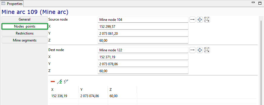
On a separate Nodes points tab of the arc properties, the arc structure is shown: links to the start and end nodes and the list arc bend points.
In the Restrictions tab, you can prevent certain equipment types from moving along the arc by checking them.

On the Mine segments tab of the arc properties, there is a link to the mine segment of which this arc is a part.

Zones
In the Zones object, a list of options for the color marking of arcs on the map is specified. For example, you can create a zone of the mine field, indicating the roads to be cleaned, and then apply this zone (color) to all arcs that require cleaning.
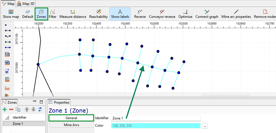
A zone is characterized by a unique identifier and color.
The Mine arcs tab of the zone properties contains a list of the mine arcs included in this zone.

Here, you can add arcs by selecting them on a mine field using the button  or remove an arc from the list (
 ).
).
Mine areas
A mine area is used to logically combine several adjacent blocks. Specific equipment/ transport unit may be assigned to areas.

A mine area in MineTwin OpenPit has following parameters:
-
A unique Identifier
-
Max active mining fronts count - a parameter that limits the number of concurrent active blocks within a mine area, even when sufficient equipment is available. For example, if 10 blocks are available for extraction, but the user sets the limit to 5, only 5 blocks will be worked on simultaneously. Work on the sixth block will only begin once operations in one of the first five are completed, and so on
Mine segments
Mine segment - an ordered set of mine arcs used to define the location of a block. A mine segment is represented by a directed polyline in three-dimensional space.

The mine segment has following General parameters:
-
Unique Identifier
-
Length, m - automatically calculated as the sum of the lengths of the mine arcs of which this segment consists
-
Mine area - a mine area to which this mine segment belongs
-
Block - a link to a block located within this mine segment
The Mine arcs tab of the mine segment properties contains a list of the mine arcs that this segment consists of.

Here, you can add an arc by selecting it on a mine field using the button or remove an arc from the mine segment ().
Layout layers
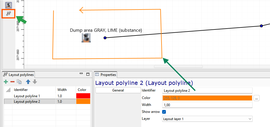
The Layout layers element of the object tree contains a list of layers, each of which includes two groups of objects: Layout polylines and Text labels. Layout layer objects serve as supplementary information when working with the map and are not involved in modeling. Layer properties allow enabling/disabling its visibility and editability.

Layout polylines
The Layout polylines group of the selected Layout layer contains a set of polylines created in the application or imported from a .dxf file. Adding a new element to the map is possible
using the  button from the palette located on the left side of the 2D map window. Polyline properties include:
-
Unique Identifier
-
Color — ability to set the color by selecting from a palette
-
Width — line thickness in pixels
-
Show arrow — function to enable/disable the display of an arrow at the last point of the polyline
-
Layer — move the layout polyline to the desired layer by selecting from the list of available layout layers
Text labels
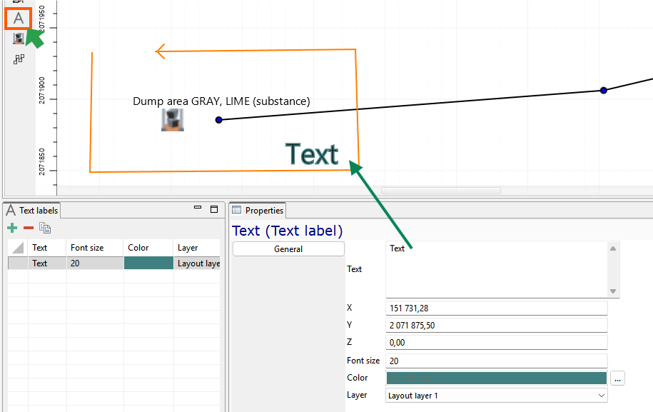
The Text Labels element lists the text labels added to the map. You can add a new item to the map using the  button from the toolbar
on the left side of the 2D map window. In the properties window you can enter the label text and set the font size and color, assignment to a layout layer from the list of those available in the scenario.
button from the toolbar
on the left side of the 2D map window. In the properties window you can enter the label text and set the font size and color, assignment to a layout layer from the list of those available in the scenario.