Define blocks
In this section, we will use the scenario we created in the previous step. Make sure you have this scenario open in MineTwin before continuing. This scenario has basic master data, a layout imported from an external file, as well as equipment types.
In this section, we will create a single block for our simple drill-and-blast method.
1. Set locations of blocks
Blocks are the places where the extraction of ore happens. In MineTwin, all blocks must be connected with the mine’s transportation network. More specifically, each block must fully or partially occupy one or several arcs. These arcs occupied by a block must be consecutive, i.e. they must follow each other in the network. In MineTwin, such a list of consecutive arcs is called a mine segment.
There are the following relationships between mine arcs, mine segments and blocks:
-
Mine arcs are a part of my mine transportation network. Every mine arc begins and ends in a mine node. Mine arcs with zero length are not allowed
-
Mine segment is just one or several consecutive mine arcs.
-
Block can occupy the whole mine segment or a part of it. In the latter case, the begin and end offsets of the block inside the mine segment must be specified
In this tutorial we will only be using a simple setup where 1 block = 1 mine segment = 1 mine arcs.
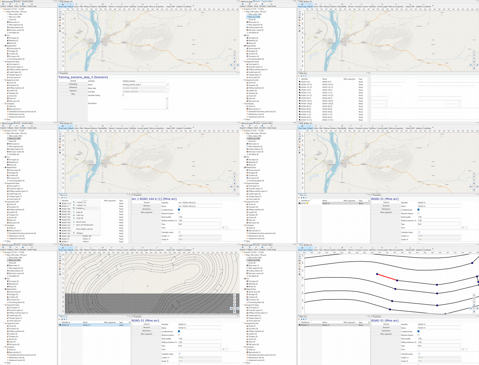
We want to place our block at a very specific location inside the mine, the road according to our DXF file is labeled ROAD-51. MineTwin offers a convenient way to find any node (a point) or an arc (a line).
You can simply navigate to the arc table by selecting the Mine Arcs table in the scenario tree, found under the Map section. Then, right-click on the mine arcs table and select "Contains" to filter to the specific arc. This filter functionality is available in all MineTwin tables.
Now that we have filtered to the specific arc we can simply double click on it and the MineTwin map view will navigate us automatically to this specific arc.
Now that we have found the arc or road where we want to set up the block, we can use the block tool in the palette. Click this tool and click one of the arcs to create a block, as shown below:
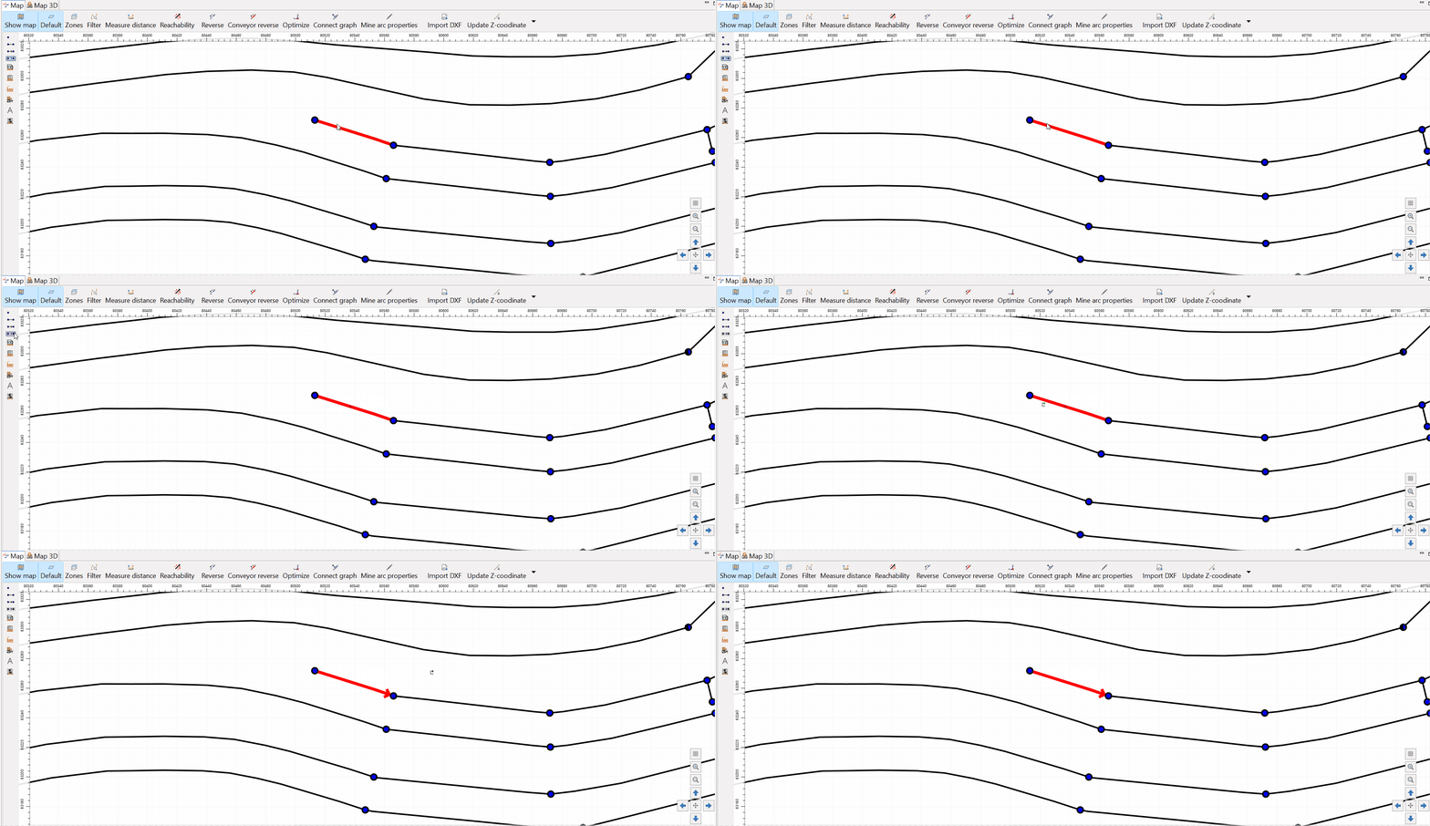
Note that, as a result, a mine segment has also been created.
However, the direction of our arcs needs to be changed to make them point in the direction of development. As you can see, the arc is pointing in the wrong direction. With the current direction, there is no way to access the starting point of the block. We can easily change this by selecting the arcs and reversing the direction using the Reverse button in the upper part of the Map view.

2. Set ore grades, densities, and fragmentation rates in blocks
Now that we have defined the location of our 3 blocks, it is time to set up the properties of material in these blocks. Let us select the Blocks item in the scenario tree, select our first block, and set the following values in its General properties section:
-
Set density of the ore to 2.6 tons per cubic meter
-
Set fragmentation rate to 1.1. The fragmentation rate is the coefficient that sets how the density decreases after the rock is blasted
-
Set the ore type to "Ore", that is, not waste rock. So, our block is a production block
The picture below shows the general properties view of our block:

Now, we can go to the Advancement type section of the block’s properties and specify the advancement type from the options available. For each option, there is a graphical representation of the process and an indication of the parameters and how they are used.
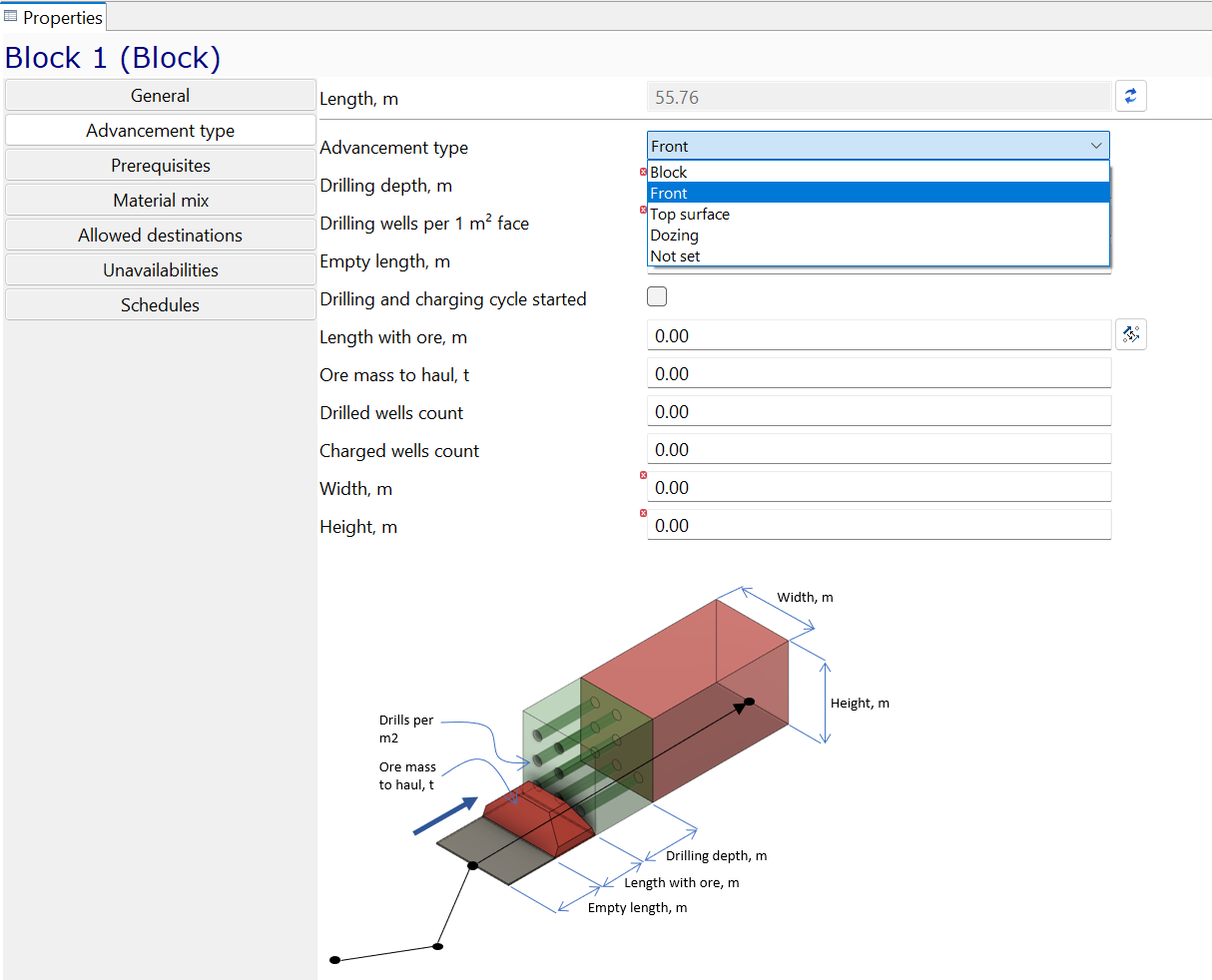
Please select the option called Front:
Next, let us set the width and height of the block’s face as well as the drilling depth and drilling wells per m2 face. :

The last thing that we will define for our block is its grade. In MineTwin, grade is represented with the mixture of materials, some being useful substances and some just empty rock. This mixture of materials can be set in the Material mix section of the block properties. Let us set the 5% grade for our block. 5% grade will be 5% of Copper material and 95% of Empty rock material. Remember that we have defined these materials at the very first step of this tutorial. This setup can be done as shown below:
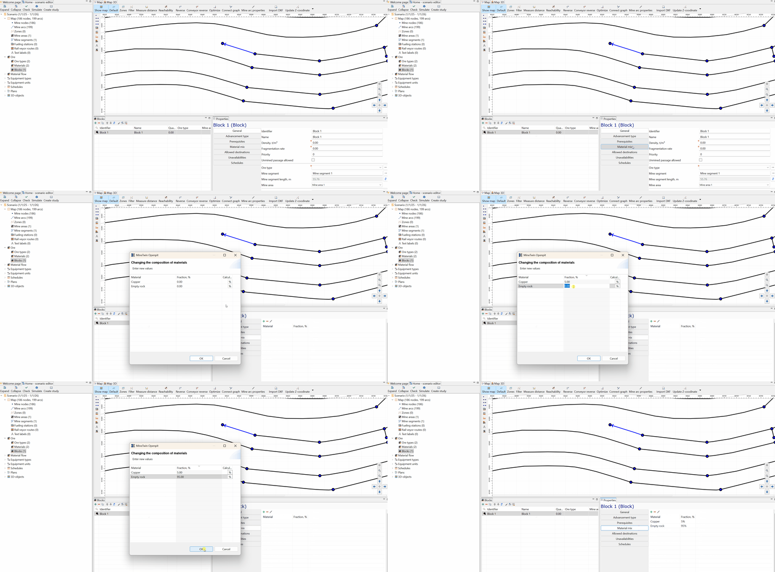
Please note that you can use the % button to calculate the last entry of the mix so that the sum of the entries adds up to 100%
Note: There are advanced options available where the setup of the block plan can be automated from existing data and layout. Contact us for more information about automating MineTwin scenario creation.
3. Review and check blocks
Let us now review the block that we have just set up. In the scenario tree, select the Blocks item and double-click on the only line in the Blocks table. MineTwin will navigate the map to this block and highlight it with red color, as shown below:
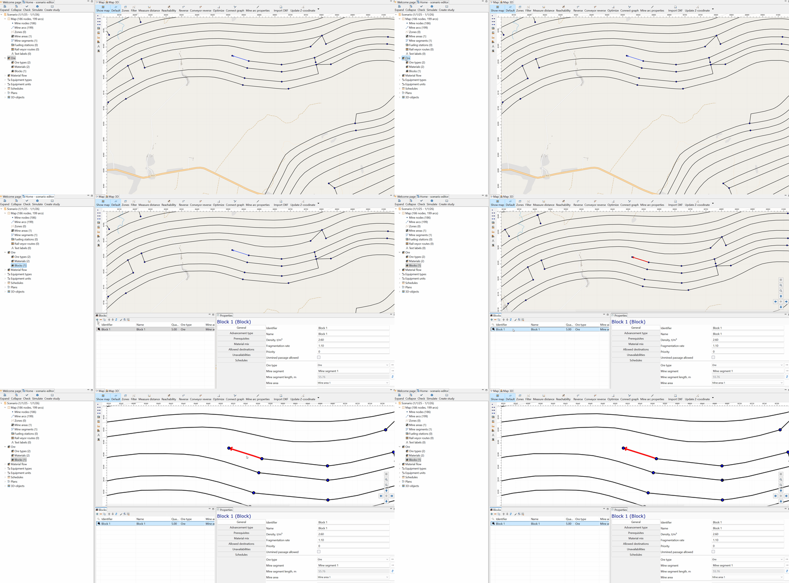
You can always hit the Esc button to deactivate any highlighting in the Map view.
Now, our scenario has become complex enough to check it for potential consistency errors and warnings. To do so, hit the Check button on top of the scenario tree:
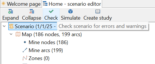
The result of this check will appear in the Errors window in the bottom left part of the application. See how our scenario has 3 errors and 2 warnings:
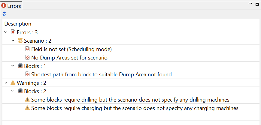
Let us go through these errors and warnings one by one:
-
The first error is one of two errors found in the scenario. It says that something might be wrong with the scheduling mode. We can skip this for now and return to it at later stages of our scenario setup.
-
The second error says that no Dump Areas are defined in our scenario. This is an error because MineTwin needs some transportation destinations for ore taken out of the blocks. Dump Areas would be the most typical such destination. We will define a Dump Area in the next step of this tutorial.
-
The third error says that no path is found from our block to any suitable Dump Area. This is an obvious consequence of the previous error.
-
Both our warnings tell that our block requires some activity, for example, drilling and charging, and there are no drills or chargers assigned in our scenario so far; we only created types for them. Let us address these issues in one of the next steps of our tutorial.
This consistency checking functionality is especially useful in the later stages of scenario setup. It guides the users by hinting what else must be set up to complete the scenario creation.
So, we have set up a block for our simulation and defined what the characteristics of the block should be. Now, we can click the Save menu button or hit Ctrl+S to save our intermediate results. You can always download the scenario file that we got so far and continue working with this tutorial later.