Scenario creation and editing
Preparing the input file
A MineTwin Underground scenario is defined in an Excel file containing all required input data.
Creating a scenario in MineTwin Underground is possible in two ways:
-
In the application interface – all source data, such as haul road network elements, equipment types and units, equipment and haul truck schedules, assignment of equipment and trucks to mining areas, etc., are added/deleted manually directly in the application. The enterprise’s haul road network topology can be added to a scenario by importing road centerlines in .dxf format.
-
By importing a template with source data – when creating a new scenario, the application allows the user to import the core data from a pre-filled Excel template.
Launching the application, loading the editing mode
To install the MineTwin Underground application on your computer, you need to unzip the "MineTwin" folder and save it on your local computer.
-
MineTwin Underground is launched from the unzipped folder by launching the MineTwin.exe application (
 ).
).
-
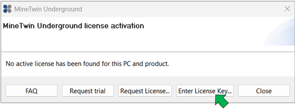
If MineTwin is launched on a PC for the first time, the system will inform you that the license was not found.
-
After clicking the license key entry button, a window will open where you can insert the 16-digit license key and click the key activation button.
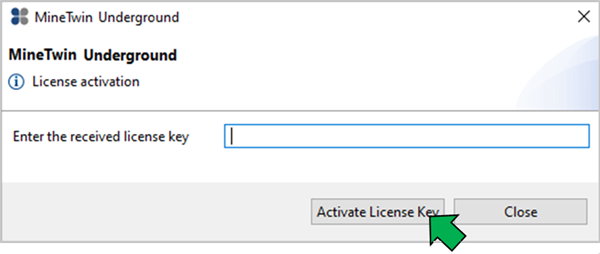
If the key is correct and is not activated on another PC, MineTwin Underground will be launched.
-
If there is no commercial license, the user can use a trial license that is valid for 30 days by clicking on the button
 .
. -
If there is no internet access when you open the app, you must connect to the internet or contact the developer for help by providing the unique PC ID that appears when you click on the license request button.
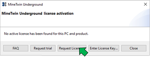
-
Copy the message text by clicking the button
 and send it to the MineTwin technical support.
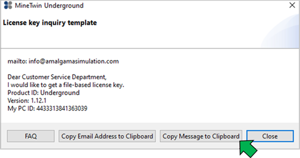
-
After launching MineTwin Underground the application’s working window will open. On the left side of the window, on the Welcome page tab, the following functions are located:
-
Create a new scenario – this function creates a new scenario file that requires manual data entry and/or data import
-
Open one of your resent scenarios – this function displays a list of recently opened scenarios on the panel for quick switching between them
-
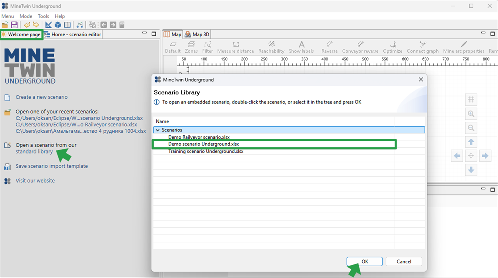
Open a scenario from our standart library – this function opens a window with a set of demonstration scenarios
-
Save scenario import template – clicking this function downloads an Excel file of the established format to your PC, which is used to fill in the core data and subsequently create a scenario by importing it.
-
Visit our website – this function redirects to the website of Amalgama LLC.
-
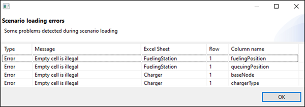
If the scenario opened contains errors, a window with a list of errors will open, indicating the name of the Excel file sheet and the number of columns and lines that contain errors. The user can open the list in a separate file and sequentially correct the errors in the downloaded Excel file or download the scenario file with errors and then fix them in the system.
After opening the scenario in the MineTwin Underground interface, the scenario editing mode window will open, the appearance of which is shown in the figure.
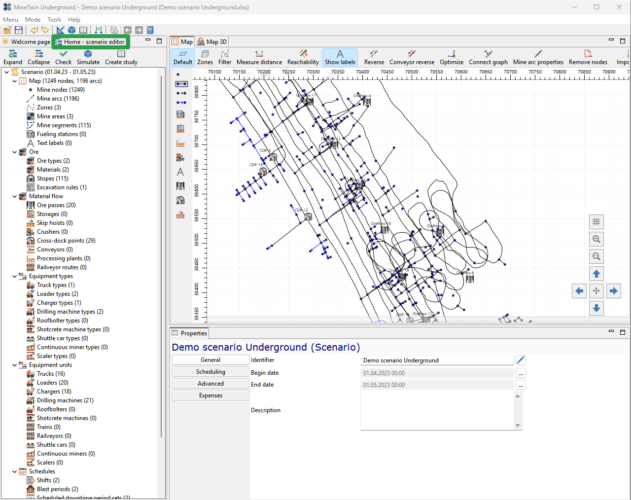
The editing mode contains several windows, which sizes can be changed by selecting the side of the window and holding down the left mouse button. Any window can be moved from one part of the interface to another by clicking on the required window with the left mouse button and holding it while moving.
To open the selected window to full screen, you need to double-click on it. To return to normal mode, double-click again or use the function Reset perspective.
Elements of the scenario editor
The scenario editor allows you to create, review, edit and save scenarios.
Tools
There is a toolbar at the top of the editing module.

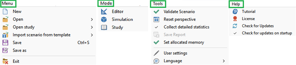
The Menu group contains the following functions:
-
Create a new scenario (
 )
) -
Open scenario (
 )
) -
Open study (
) -
Import scenario from template (
 ) – this function creates a new scenario by importing the filled-in source data template
 -
Save scenario (
 )
) -
Save As Copy (
) -
Exit (
 ).
).
The Mode group is used to switch between the modes:
-
Simulation (
 )
) -
Editor (
 )
) -
Study (
 )
)
The Tools group contains the following functions:
-
Validate scenario after its creation/editing (
 )
) -
Collect detailed statistics (
 ) — the ability to view the status of all equipment units at any moment in time
 -
Save Report (
 )
) -
Set allocated memory (
) - the function allows you to set the amount of RAM used during simulation -
User settings (
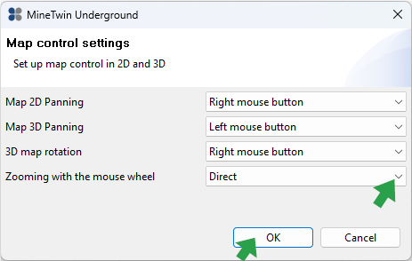
 ). The user can choose the map panning/rotation method that suits them best in 2D and 3D modes
-
Language switch (Russian and English are available)
The Help group contains:
-
Link to the Tutorial
-
License information, including PC ID that is needed to renew the license
-
Check for Updates — manual check for updates
-
Check for updates on startup — enable this option to have the software automatically check for updates each time it starts.
If it is necessary to undo/redo a canceled action, use the buttons  .
.
The buttons  duplicate the mode switching options available in the Mode group.
The button  synchronizes graphs in the simulation mode.
The button  allows the user to upload simulation results to an Excel file (general statistics, costs, equipment performance indicators, etc).
The buttons  provide access to previously viewed directories and objects.
The button  searches any scenario element by its name.
Model tree
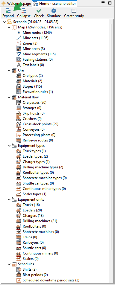
All scenario objects and entities data (parameters of stopes, dump areas, equipment units, equipment operation schedules, etc.) are displayed in the form of a tree and are grouped by types. For each type of object/entity, the number of units of the object/entity is shown.
Blocks of the model tree can be expanded/minimized for easy viewing.
Objects
The Objects window displays a list of all units of objects/entities of the type selected in the object tree, for example, a list of all loaders, stopes, etc.
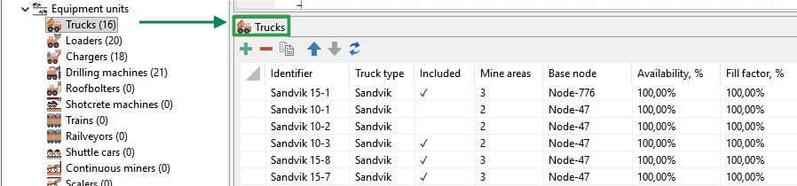
At the top of the Objects window, there is a toolbar with functions for adding, deleting, copying objects, moving objects up or down and refreshing values.

When you hover the mouse over the icon, the tooltip for this button will be displayed.
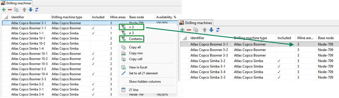
The data table supports sorting for all columns as well as filtering. To apply a filter, right-click a row in the desired column and set the required filter in the pop-up window.
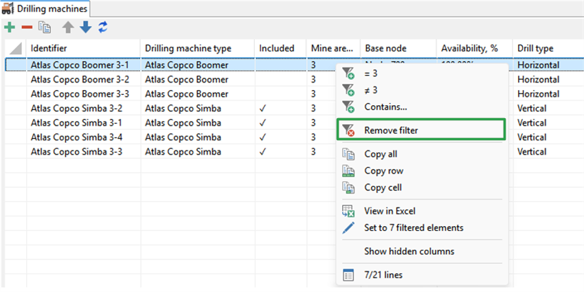
To remove the filter, use the Remove filter button in the pop-up window.
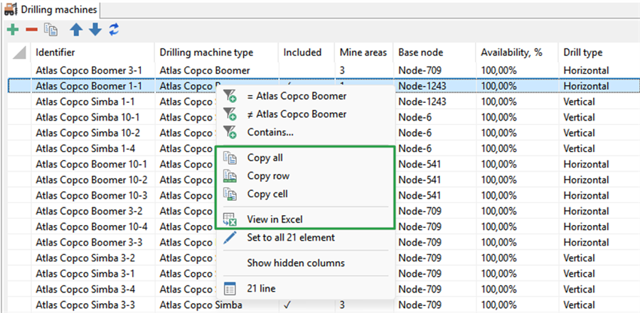
The contents of the entire table, selected rows, or individual cells can be copied or exported to Excel for further analysis.
Most columns in the table are editable. To edit the value in a single cell, left-click it and make the necessary change. To edit all values in a column, use the Set to all items button — for example, to set the same explosives warehouse for all charging machines. You can also filter the rows (for example, by equipment type) and assign a value in the column only to the filtered cells — for instance, to specify the same work area for all trucks of a certain type.
Properties
The Properties window displays and allows editing of the properties of the object (entity) selected in the object list. To edit an object’s properties, select the object in the list and switch to the Properties window.
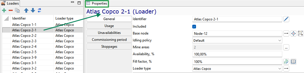
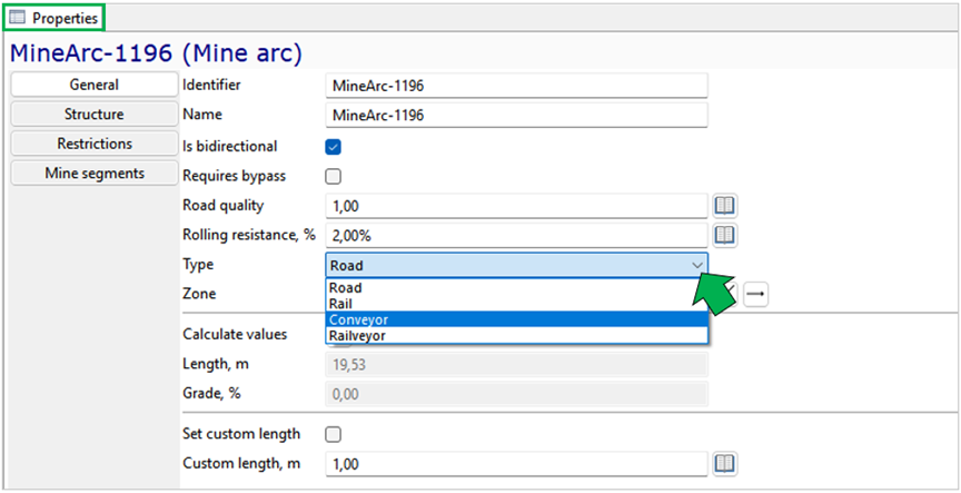
To change the parameters, the values of which are limited by the enumeration, the required value is selected from the drop-down list and removed by clicking on the cross to the right of the field.
To update the data, use the button  .
.
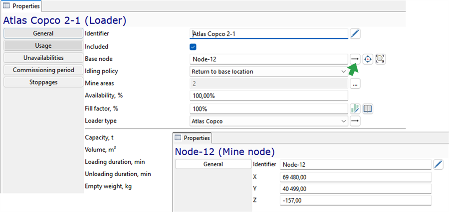
From the properties of the object unit, you can go to the properties of related objects, for example, from the properties of the equipment unit to the properties of the type of this equipment unit or the properties of its base node. To do this, click on the arrow to the right of the field.
The button  allows you to define a different base node by selecting it on the map in 2D mode.
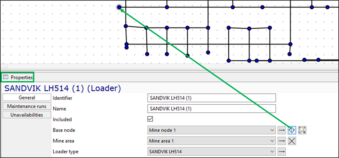
The button  highlights the selected node in the graphical editor (on a 2D map).
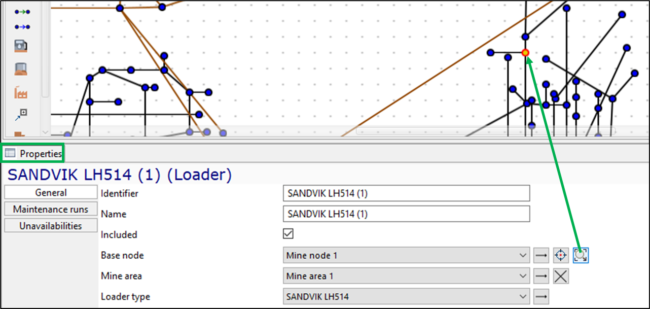
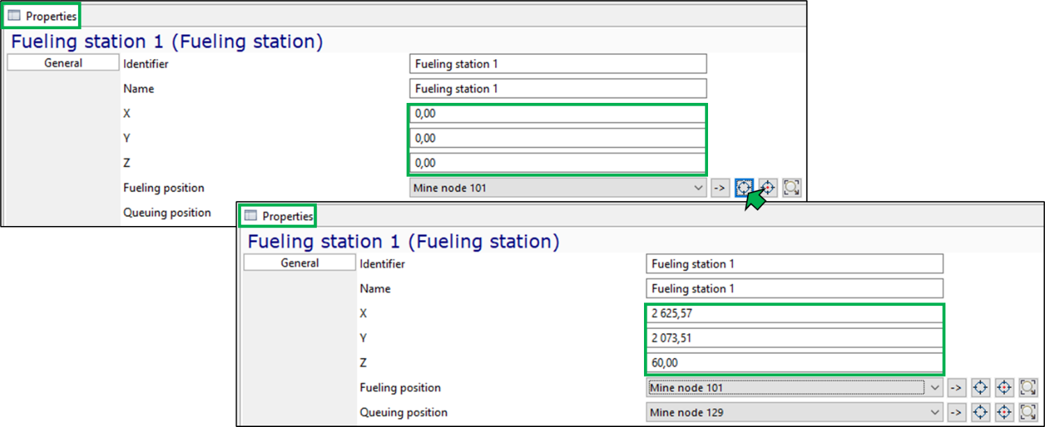
To move the object unit on the mine map to the point of its base node, use the button  .
.
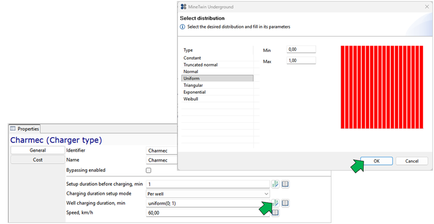
All durations in MineTwin can be set to a constant value or one of the distributions (normal, truncated normal, uniform, triangular).
To set the duration, you need to go to the pop-up window by clicking on the  button to the right of the duration value field and select the appropriate distribution in the window that appears.
Alternatively, you can edit the value directly in the field.
button to the right of the duration value field and select the appropriate distribution in the window that appears.
Alternatively, you can edit the value directly in the field.
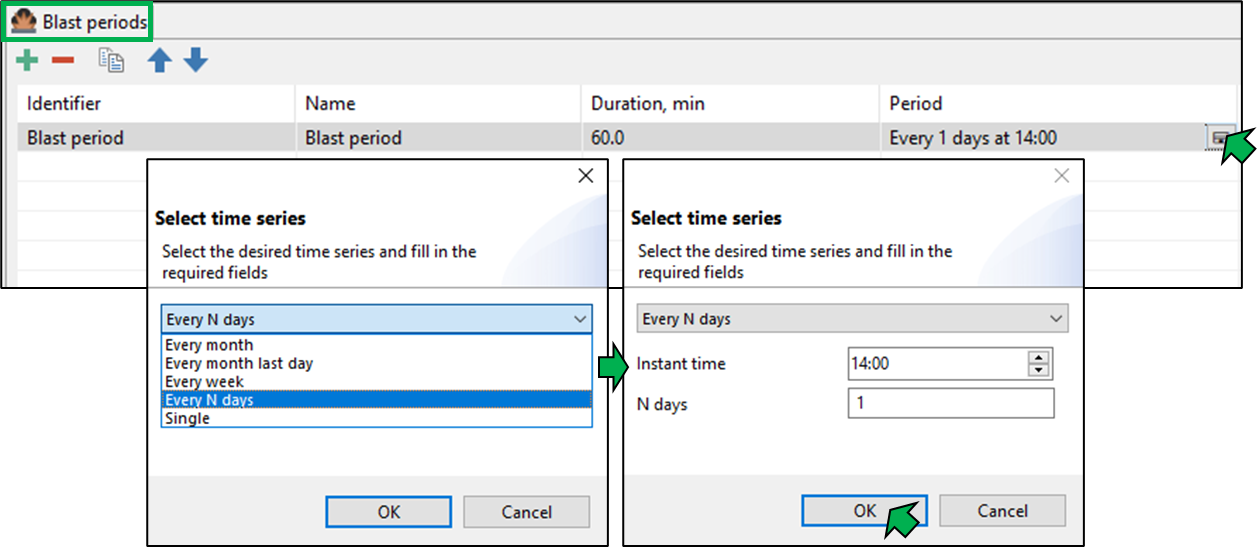
The time of occurrence of all periodic events in MineTwin can be set by the exact time or by some frequency (every n-th day of the month, every last day of the month, every week, every n days).
Map
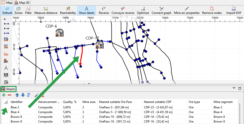
The Map window displays a mine plan in two dimensions. The plan in this mode is editable.
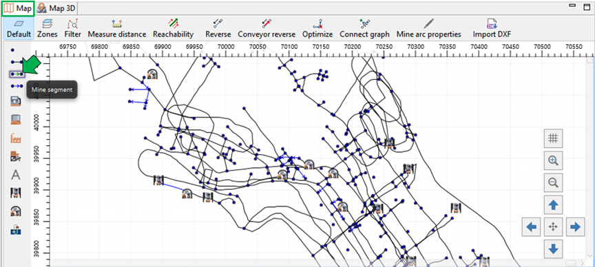
Viewing control functions
Zooming in/out of the mine plan is performed by the mouse wheel while holding down the Ctrl key. The plan is moved with the mouse while holding down the right mouse button.
In the lower-right corner of the window, there is a map display control panel.
The button  allows you to enable/disable the coordinate grid and the ruler along the window outline.
The button  allows you to center the map.
The buttons  zoom in and out of the map.
The buttons  allow you to move the map up, down, right, and left.
The top of the Map window contains a toolbar for working with transportation network graphs.
The button  activates the illumination of the mine arcs by default, and the button
  activates the illumination of the arcs by mine zones.
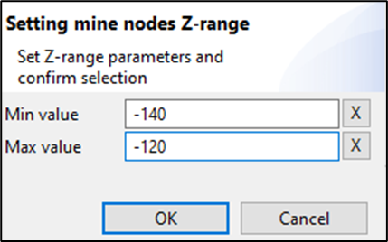
In the graphic editor MineTwin Underground, the viewing of individual sections of the mine field located at a given depth is available. The button  is used to set the range in the Z-coordinate of the mine nodes for viewing, for example, from -140 to -120.
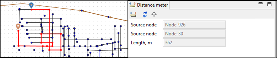
The button  allows us to determine the shortest distance between two nodes of the mine field. After clicking on this
button, a label
allows us to determine the shortest distance between two nodes of the mine field. After clicking on this
button, a label  appears, which must be placed on the node of the beginning of the path and clicked with the mouse.
Then the second label
appears, which must be placed on the node of the beginning of the path and clicked with the mouse.
Then the second label  will appear, which must be set on the destination node. After that, the route between the nodes
will be highlighted on the map, and information about the distance between the selected mine nodes will appear in the Distance meter window that opens.
will appear, which must be set on the destination node. After that, the route between the nodes
will be highlighted on the map, and information about the distance between the selected mine nodes will appear in the Distance meter window that opens.
To exit the distance measurement mode, use the Esc key.
The button  highlights isolated sections of the transport network in different colors.
Map editing functions
The button  allows you to quickly change the direction of the stope.
The button  allows you to quickly change the direction of the conveyor.
The button  optimizes arc inflection points - removes inflection points that are on the same line between two consecutive inflection points of selected
mine arcs or all arcs of the scenario if no arc is selected.
optimizes arc inflection points - removes inflection points that are on the same line between two consecutive inflection points of selected
mine arcs or all arcs of the scenario if no arc is selected.
The button  creates a connection between a mine field arc and a node/arc, if the distance between them is less than 2.5 meters (by default). When the selected arc is merged with
another arc’s node, the former is split into two. If no arcs are selected, pressing this button connects all nearby arcs of the transport network according to the described rule.
creates a connection between a mine field arc and a node/arc, if the distance between them is less than 2.5 meters (by default). When the selected arc is merged with
another arc’s node, the former is split into two. If no arcs are selected, pressing this button connects all nearby arcs of the transport network according to the described rule.
The button  opens a dialog box for setting the basic properties of a mine arcs group. To do this, use the mouse to select the desired set of mine arcs on the map, click this button,
activate the editable parameters, and change the values to the desired ones.
opens a dialog box for setting the basic properties of a mine arcs group. To do this, use the mouse to select the desired set of mine arcs on the map, click this button,
activate the editable parameters, and change the values to the desired ones.
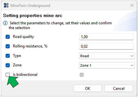
You can use the dialog box to set the following parameters in bulk:
-
Road quality
-
Rolling resistens,%
-
Type: road, rail, conveyor or railveyor
-
Zone
-
Is bidirectional - parameter that indicates whether movement along the mine arc in both directions is possible
Importing graphical data in .dxf format
MineTwin Underground supports the import of graphic data from third-party IT systems in .dxf format. By clicking on the button  , a dialog box opens where you can select the desired dxf file,
select the required layers, and import them into the scenario. If the parameters of the imported topology are specified in a non-metric system (e.g., feet), you need to multiply the coordinates by the appropriate conversion factor to convert them to metric units.
When importing geometry, the following line types can be assigned:
, a dialog box opens where you can select the desired dxf file,
select the required layers, and import them into the scenario. If the parameters of the imported topology are specified in a non-metric system (e.g., feet), you need to multiply the coordinates by the appropriate conversion factor to convert them to metric units.
When importing geometry, the following line types can be assigned:
-
ROAD — road axis for the movement of self-propelled mobile equipment
-
RAIL — railroad track axis
-
CONVEYOR — conveyor line axis
-
RAIL_VEYOR — railroad track axis for rail‑conveyor systems
-
LAYOUT — polylines of the layout layer used as auxiliary elements when working with the Map; they are not involved in simulation
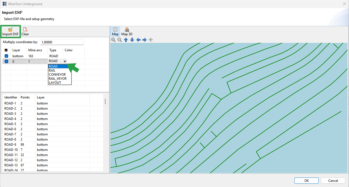
By default, all imported lines are assigned the ROAD type.
Left toolbar (palette)
The left panel of the editor window (Map) contains objects that can be added to the enterprise plan: mine nodes, arcs and segments, stopes, fueling and recharging stations, storages, processing plants, crushers, blenders, ore passes, cross-dock points and skip hoists.
A mine polyline arc and a layout polyline are created by successively placing vertices/points of the polyline with the mouse. Drawing is completed by double‑clicking the left mouse button. If you start drawing a polyline arc from a transport network node and/or finish on an existing similar node, the line connects to these nodes and arcs, forming a single network.
To add an stope or a mine segment, left‑click the corresponding object on the palette, then left‑click the desired arc on the map.
To add other objects from the palette, left‑click the object on the palette, then click at the location on the map where you want to place the object.
In the Map window, multiple selection and moving of objects is available. To do this, select the objects with the mouse and move them using the keyboard arrow keys.
When you select the object unit in the list of objects window, the corresponding object is highlighted on the map.
Map 3D
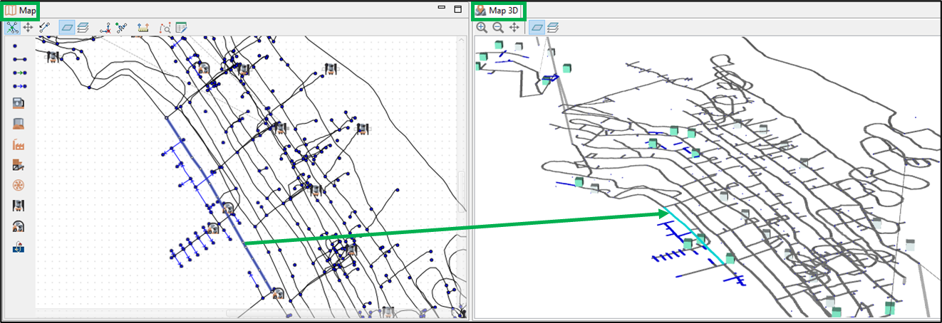
The Map 3D window displays a mine plan in three dimensions. The plan in this mode is available only for viewing.
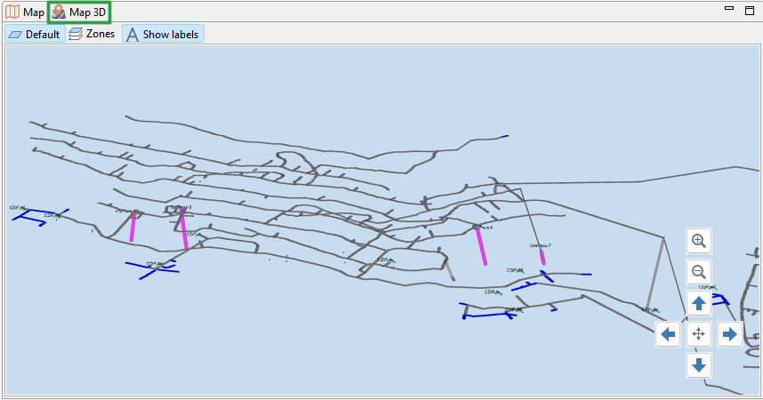
The plan is moved with the mouse while holding down the left mouse button, rotation is done while holding down the right mouse button.
The model display control panel is located in the lower-right corner of the window.
The button allows you to center the 3D map.
The buttons  allows you to zoom in and out on the 3D map of the mine.
The button activates the illumination of the mine arcs by default, and the button
activates the illumination of the arcs by mine zones, hides/shows text labels.
Maps in 2D and 3D are synchronized: when you select an object on one map, it is highlighted on the other.
Errors
After creating/editing a scenario, you need to check its correctness using the Validate scenario button in the Tools button menu on the toolbar or by using the Check button in the editor toolbar.

If the data is set incorrectly or there is not enough data, an error message will appear, a list of which will be shown in the Errors window.
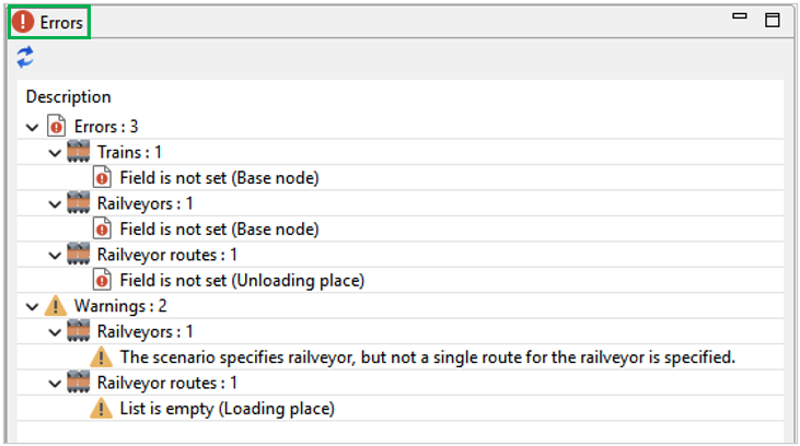
Error messages can be of two types:
-
errors that make scheduling impossible;
-
warnings about the lack of some data that do not interfere with scheduling.
Clicking on each line of the error list in the Properties window opens the properties of the object in which the error occurred, and the user can quickly fix it.
The button  in the upper right corner of the Errors window serves to update the error list after they have been fixed.
Scenario
The Scenario object tree element contains global parameters related to the scheduling and simulation of an underground mine.
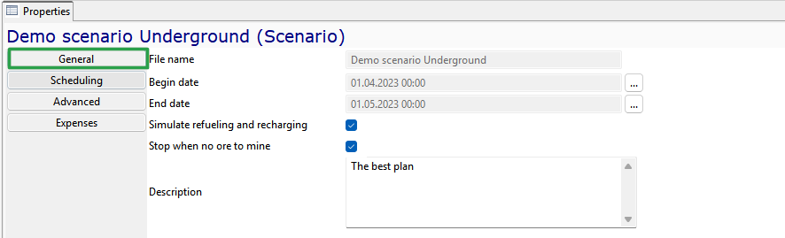
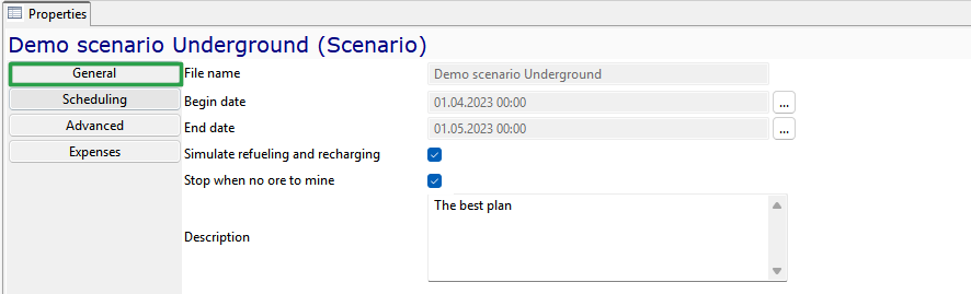
On the General tab, you will find:
-
File name
-
Begin and end date - date and time for planning and simulation
-
Simulate refueling and recharging - when checked, refueling and recharging are simulated; when unchecked, fuel and energy demand is calculated but the movement to the station and the refueling/recharging process are not simulated
-
Stop when no ore mine - stop the simulation if there is no ore remaining in the mining fronts, even if specified end date has not yet been reached
-
Description — comments on the scenario (optional)
The Scheduling tab contains parameters that define the planning rules:
-
Scheduling mode — one of the possible scheduling modes:
-
Target adherence type — one of two options for target adherence policy:
-
Maximize mass with exact match to grade — the scheduler tries to meet the planned ore quality and volumes. It does not exceed planned production volumes even if there are free work faces and equipment. If work faces, equipment, or ore of the required quality are insufficient, the scheduler prioritizes achieving the target ore quality, even at the cost of reducing tonnage
-
Maximize mass regardless of grade — the scheduler maximizes production regardless of quality. It seeks to reach target volumes for both ore and waste and to avoid situations where one target is missed while the other is greatly exceeded. After hitting both targets, equipment is distributed approximately evenly between ore and waste to maximize both
-
-
Excavator relocation distance quantum, m — this parameter defines the search radius for an excavator’s next work location. After an excavator completes work in a block, its next work location is searched for within the specified radius. When all blocks within this radius have been processed, the radius is doubled, and the search for a work location is conducted within the new, doubled radius. If no work is found there either, the search is performed across any range
-
Percentile for RV estimation, % – a technical parameter that defines the fluctuation range of random variables. The result of the calculation is a number that does not vary during the planning process. For example, with a uniform distribution of operation duration from 5 to 10:
-
If the percentile is set to 0% – the minimum possible value of 5 will be used in planning
-
If the percentile is set to 100% – the maximum possible value of 10 will be used in planning
-
If the percentile is set to 20% – the value 6 will be used in planning, because with 20% probability in a uniform distribution from 5 to 10, the value will be between 5 and 6
-
If the percentile is set to 40% – the value 7 will be used
-
-
Haulage scheduling mode:
-
Shiftwise only – tasks are generated only at the start of each shift and are not updated during the shift
-
Dynamic only – a new task is assigned to each haul truck immediately upon completion of its previous trip
-
Shiftwise and dynamic – tasks are generated on a shift basis but are supplemented dynamically if a truck becomes idle (e.g., due to excavator breakdown or early completion of work).
-

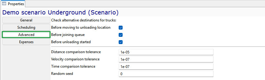
The Advanced tab contains additional technical settings
When to check the fill level of the planned dump location and choose alternative dump locations for trucks:
-
Before moving to unloading location - when this parameter is enabled, trucks will check the fill level of the scheduled dump area/ ore pass before beginning to unloadw
-
Before joining queue - when this parameter is enabled, trucks will check the fill level of the scheduled dump area/ ore pass before joining the queue for unloading
-
Before unloading started - when this parameter is enabled, trucks will check the fill level of the scheduled dump area/ ore pass before starting to travel to the dump area/ ore pass.
-
Precision settings for comparing Distance, Velocity, and Time during simulation
-
Random seed — an initial value used in random number generators to create a sequence of random numbers. It serves as a "starting point" that determines which numbers will be generated. Using the same random seed ensures that the simulation results for a scenario are identical on every simulation run. Running the same scenario with a different random seed may produce different simulation results.
On the Expenses tab, you specify:
-
Monthly fixed costs of the pit/mine, USD
-
Fuel price, USD/liter to be used when calculating fuel costs
-
Power price, USD/kWh - for charging self-propelled equipment with electric motors (rechargeable batteries).

Map
The Map model tree element contains the following elements of an underground mine:
-
Mine nodes
-
Mine arcs
-
Zones
-
Mine areas
-
Mine segments
-
Layout layers
Mine nodes
Mine node - an element of the mine transport network graph which corresponds to one point in two-dimensional space.

The mine node is characterized by the following parameters:
-
Unique identifier
-
X-, Y- and Z-coordinates
Mine arc
Mine arc - an element of the transport network graph that connects two mine nodes.
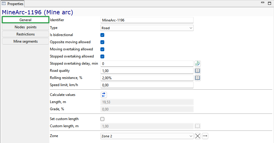
The mine arc is characterized by the following parameters:
-
Unique Identifier
-
Type — one of the following types: Road (non-rail), Rail, Conveyor or Railveyor
-
Is bidirectional — parameter indicating whether travel along this mine arc is possible in both directions (two-way road)
-
Opposite moving allowed — a parameter specifies whether simultaneous movement in the opposite direction is allowed. If not, the equipment will stop in front of the arc to allow those traveling in the opposite direction to pass
-
Moving overtaking allowed — a parameter specifies whether passing of slower vehicles traveling in the same direction is permitted on this arc
-
Stopped overtaking allowed — a parameter specifies whether a moving vehicle may overtake or bypass a stopped vehicle on this arc
-
Stopped overtaking delay, min — a parameter defines the additional delay required for a vehicle to overtake or bypass a stopped vehicle on this arc
-
Road quality — a factor that adjusts the base speed of equipment when traveling along this mine arc
-
Rolling resistance, % — the resistance that occurs when tires of self-propelled wheeled equipment roll on the road surface. This parameter affects the equipment’s travel speed when the speed calculation rule "Rimpull curve based" is applied
-
Speed limit, km/h — maximum speed of movement for all moveable equipment on this arc. The actual speed can be lower due to individual equipment settings
-
Length — system-calculated length of the segment, taking into account the mine arcs it comprises
-
Grade, % — arc gradient (slope) is automatically calculated by the system as the ratio of the vertical rise (difference in z-coordinates) to the arc length, expressed as a percentage
-
Set custom length — parameter allowing to set an arbitrary length for the mine arc, disregarding actual coordinates and scaling
-
Custom length,m — conditional/override length of the mine arc
-
Zone — zones serve for color-coding mine arcs. For example, a user can create a transport network zone indicating roads requiring clearing and then apply this zone (color) to all arcs that need clearing
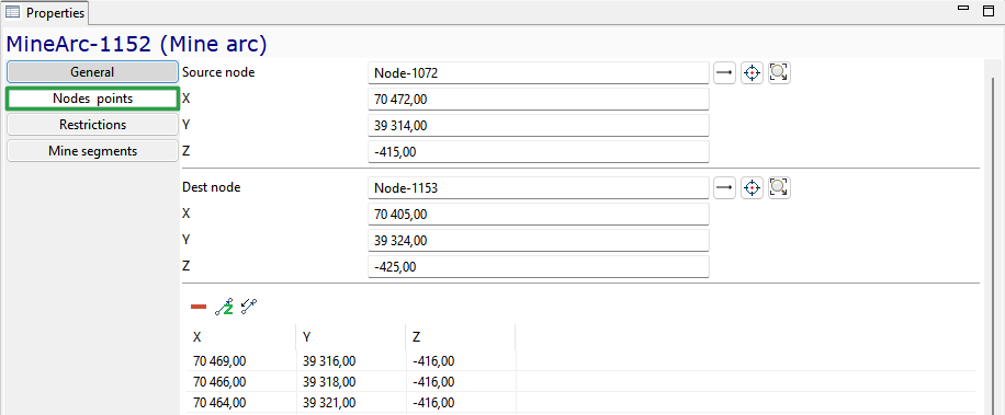
A separate tab of the properties of the mine arc displays the Nodes points of the arc - references to the start and end node of the mine arc and the list of broken line points (arc inflection points).
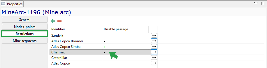
In the Restrictions group, you can prohibit the movement of certain types of equipment along the arc of the transport network by checking the box next to them.
Reference to the mine segment of which this arc is a part is displayed in the Mine segments tab of the arc properties.

Zone
The Zone object defines a list of color options for arcs on the mine field map. For example, a user can create a mine field zone that represents roads that need to be cleared, and then apply this zone (color) to all arcs that require clearing.
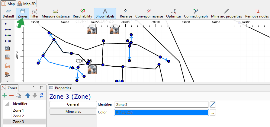
The zone is characterized by a unique Identifier and Color.
The Mine arcs tab of the zone properties contains a list of the mine arcs included in this zone.
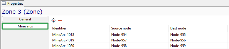
Here, you can add arcs by selecting them on a mine field using the button  or remove an arc from the list
(
or remove an arc from the list
( ).
).
Mine area
A mine area is used to logically combine several adjacent stopes. Specific equipment/ transport unit may be assigned to areas.

A site in MineTwin Underground is characterized by the following main parameters:
-
unique Identifier
-
Maximum active mining fronts count in simultaneous operation is a parameter that limits the work on the site, even if there is enough equipment. For example, there are 10 workings available for mining, but the user has set a limit of 5. In this case, only 5 workings will be mined. Work on the sixth working will begin only after one of the first 5 workings has been completed, and so on.
Mine segment
Mine segment - an ordered set of mine arcs used to define the location of a stope. A mine segment corresponds to a directed broken line in three-dimensional space.

The mine segment is characterized by the following main parameters:
-
unique Identifier
-
Length, m - automatically calculated as the sum of the lengths of the mine arcs of which this segment consists
-
Mine area - a mine area to which this mine segment belongs
-
Stope - a reference to a stope to which this segment corresponds.
The Mine arcs tab of the mine segment properties contains a list of the mine arcs that this segment consists of.

Here, you can add arcs by selecting them on a mine field using the button or remove an arc from the mine segment
().
Layout layers
The Layout layers element of the object tree contains a list of layers, each of which includes two groups of objects: Layout polylines and Text labels. Layout layer objects serve as supplementary information when working with the map and are not involved in modeling. Layer properties allow enabling/disabling its visibility and editability.

Layout polylines
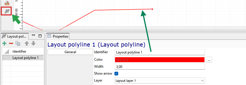
The Layout polylines group of the selected Layout layer contains a set of polylines created in the application or imported from a .dxf file. Adding a new element to the map is possible
using the  button from the palette located on the left side of the 2D map window. Polyline properties include:
-
unique Identifier
-
Color — ability to set the color by selecting from a palette
-
Width — line thickness in pixels
-
Show arrow — function to enable/disable the display of an arrow at the last point of the polyline
-
Layer — move the layout polyline to the desired layer by selecting from the list of available layout layers
Text labels
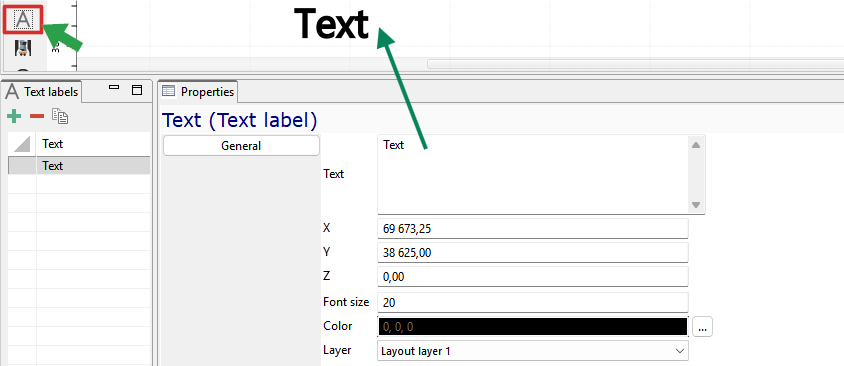
The Text Labels element lists the text labels added to the map. You can add a new item to the map using the  button from the toolbar
on the left side of the 2D map window. In the properties window you can enter the label text and set the font size and color, assignment to a layout layer from the list of those available in the scenario.
button from the toolbar
on the left side of the 2D map window. In the properties window you can enter the label text and set the font size and color, assignment to a layout layer from the list of those available in the scenario.
Energy
Energy object tree group contains the following mine/pit elements:
-
Fueling stations
-
Recharging stations
-
Recharging bays
-
Fixed battery types
-
Swappable battery types
Fueling station
Fueling station - a piece of stationary equipment designed for refueling transport and equipment units.
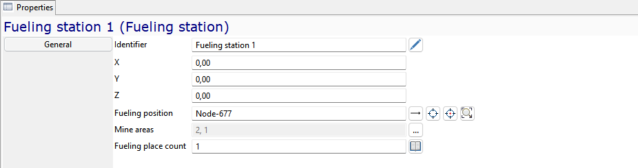
The fueling station has the following parameters:
-
unique Identifier
-
X-, Y- and Z— coordinates
-
Fueling position — link to the mine node where the equipment unit is located while refueling at the fueling station
-
Mine areas - when specifying areas, this fueling station will only serve self-propelled equipment that belong to those areas
-
Fueling place count - number of simultaneous refueling positions
Recharging stations
Recharging stations — a transport infrastructure element designed for recharging batteries that are structurally integrated into the equipment and cannot be removed from it.
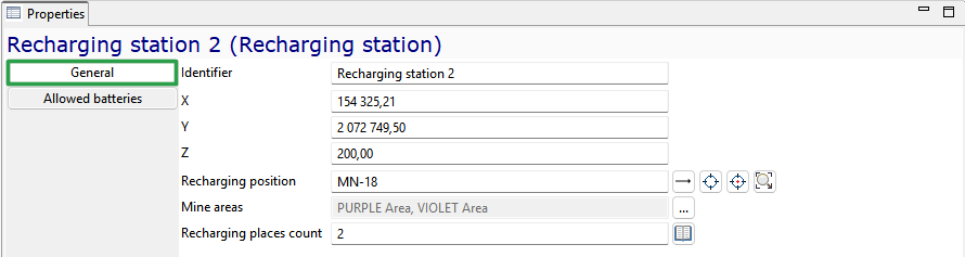
The General properties of a recharging stations include:
-
unique Identifier
-
X, Y, and Z— coordinates of the transport network node at which the station is located
-
Recharging position — identifier of the transport network node at which the equipment unit is positioned during battery recharging
-
Mine areas — mine areas whose equipment may be recharged at this station
-
Recharging places count — number of equipment units that can be recharged simultaneously at this station.
On the Allowed batteries tab, you may select from the list the types of fixed batteries that can be recharged at this station. The types and specifications of fixed batteries are populated in the Fixed battery types object group.

To select the permitted types, tick the Select field. The  button allows you to select the entire list of fixed battery types,
while the
button allows you to select the entire list of fixed battery types,
while the  button clears all selections.
Recharging bays
Recharging bays — a transport infrastructure element designed for exchanging depleted batteries with fully charged ones and for recharging discharged batteries.
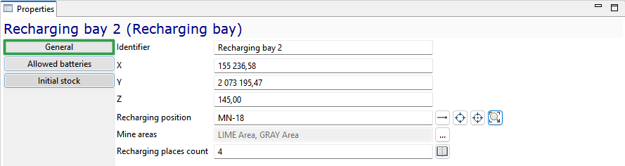
The General properties of a recharging bays include:
-
unique Identifier
-
X, Y, and Z— coordinates of the transport network node at which the station is located
-
Recharging position — identifier of the transport network node at which the equipment unit is positioned during battery recharging
-
Mine areas — mine areas whose equipment may be recharged at this station
-
Recharging places count — number of equipment units that can be recharged simultaneously at this station.
On the Allowed batteries tab, you may select from the list the types of swappable batteries that can be recharged at this station. The types and specifications of swappable batteries are populated in the Swappable battery types object group. To select the permitted types, tick the Select field.

The button allows you to select the entire list of swappable battery types, while the button clears all selections.
On the Initial stock tab, specify the quantity of fully charged batteries of each type (if any) available at the start of the simulation. If the station has no stock of charged batteries, this tab is left blank.

Fixed battery types
Fixed battery types are characterised by the following General properties:
-
unique Identifier
-
Battery capacity, kWh — the capacity of a fully charged battery
-
Charging threshold level, % — the battery charge level at which the equipment unit starts travelling to a recharging station
-
Charging rate, kW — the charging power rate at which energy is transferred from the station to the battery per hour.
Swappable battery types
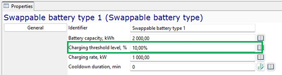
Swappable battery types are characterised by the following General properties:
-
unique Identifier
-
Battery capacity, kWh — the capacity of a fully charged battery
-
Charging threshold level, % — the battery charge level at which the equipment unit starts travelling to a recharging bay
-
Charging rate, kW — the charging power rate at which energy is transferred from the station to the battery per hour.
-
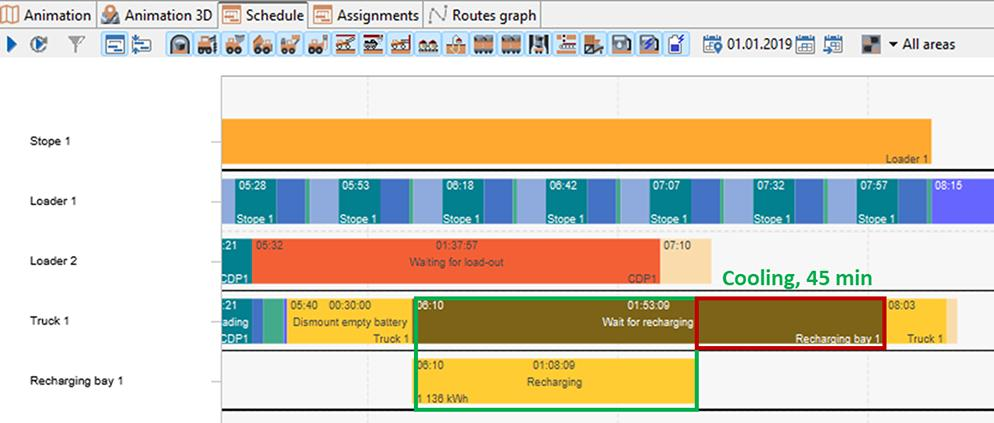
Cooldown duration, min — the time during which a swappable battery cools down after charging. The battery cannot be installed on an equipment unit until this period has elapsed.
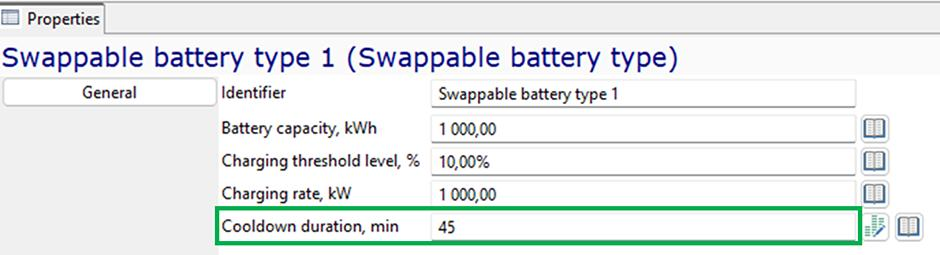
The Cooldown duration, min parameter applies only to swappable batteries. Fixed batteries do not require a separate cooldown setting: any cooling intervals during charging are typically accounted for in the charging rate.
If Cooldown duration, min is set to 0, the battery can be installed on an equipment unit immediately after charging is complete.
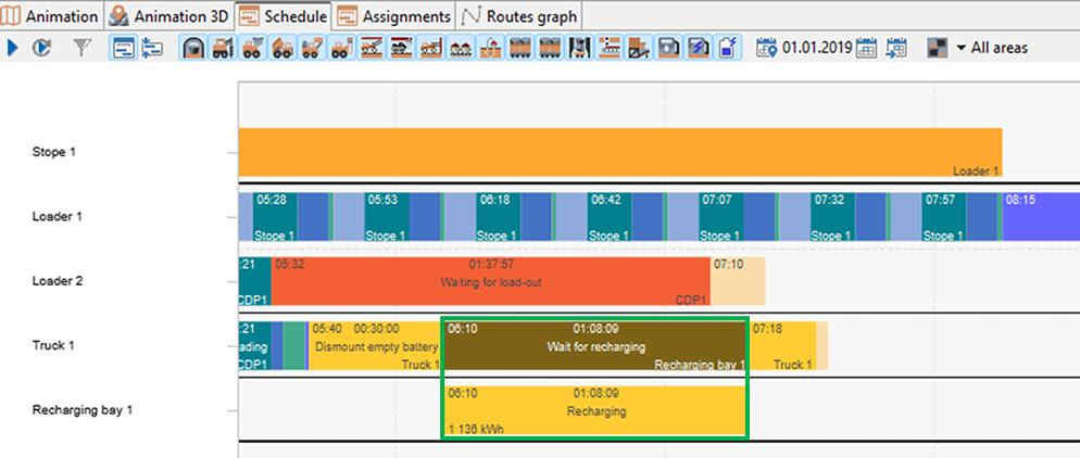
If a non-zero cooldown duration is specified, the equipment unit waits for the battery to cool down before installation. In this example, the cooldown duration is 45 minutes.
Ore
The Ore model tree element contains the following elements of an underground mine:
-
Ore types
-
Materials
-
Stopes
-
Excavation rules
Ore types
Ore - all minerals and empty rocks that are broken up during mining operations. The Ore types object tree element contains a list of all ore types that can be used for scheduling.

For each ore type, the following properties must be set:
-
Unique Identifier
-
Ore category: production or development.
Material
Material - a type of substance contained in the ore mass. The Material object tree element contains a list of all materials that can be used for scheduling.

The following properties must be set for each material:
-
unique identifier
-
One of two logical types: substance or empty rock.
Stope
In MineTwin Underground terms, a stope is where the equipment performs operations. On the mine plan, the stope corresponds to the mine segment.
General parameters
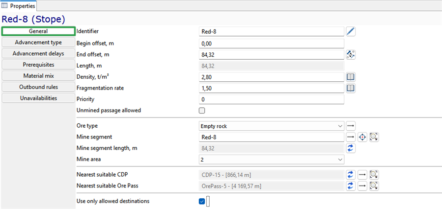
The stope is characterized by the following main parameters:
-
unique identifier
-
Begin offset, m – distance from the begin of the stope that was already developed at the start of planning/simulation, determines the working place in the stope
-
End offset, m – distance from the beginning of the stope, determines the end of the stope for development. For example, the length of the stope is 60 meters, the begin offset is 20 meters, and the end offset is 55 meters. It means that the equipment will work in the stope only on the length from 20 to 55 m because 20 m is already finished, and the last 5 m is not available for work.
-
Density, t/m3 - ore mass per unit volume minus the volume of pores, voids and cracks, in t/m3
-
Fragmentation rate - coefficient characterizing the increase in the volume of ore mass during destruction (blasting or cutting by continuous miner)
-
Priority determines the sequence of mining operations, all other things being equal: mines with a lower priority will be planned earlier than mines with a higher priority
-
Unmined passage allowed - the function is used in case of an increase in the section of the stope, provides through passage for permitted types of equipment
-
Ore type - one of the possible types of ore mass in the scenario
-
Mine segment - reference to the mine segment that corresponds to the stope
-
Mine segment length, m is equal to the length of the mine segment, which corresponds to the stope
-
Mine area - selection of the area to which the mine workings belong
-
Nearest suitable CDP - the nearest overload point to the mine is displayed, where the mine mass can be sent from the mine
-
Nearest suitable ore pass - the closest ore pass to the stope that can take on the ore type of the stope. The nearest suitable ore pass is determined automatically
-
Use allowed destinations – when this feature is enabled, the rock mass from the workings will be transported only to the ore passes/CDP points specified in the Outbound rules in the order specified in the tab
Advancement type
Parameters characterizing the way of the stope advancement and specifying the initial state of the stope at the moment of scheduling start must be necessarily specified for the stope.
First of all, you should set the advancement type of the stope. In MineTwin Underground, the following advancement types are developed:
-
Excavation – front advancement of the stope with horizontal drilling
-
Cleaning – stope advancement with vertical or diagonal drilling that is performed according to the rules set for the whole stope
-
Composite – stope advancement with vertical or diagonal drilling that is performed according to the rules set for each drill ring
-
Backfill – filling spent stopes with laying material after excavation of rock mass from them
-
Continuous – cutting the ore with a continuous miner forward with subsequent ore excavation
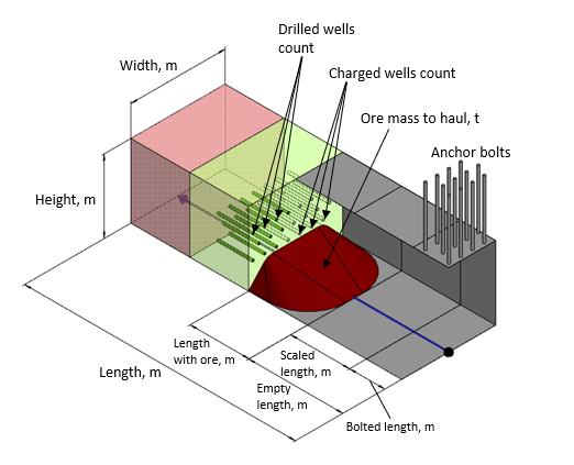
Excavation
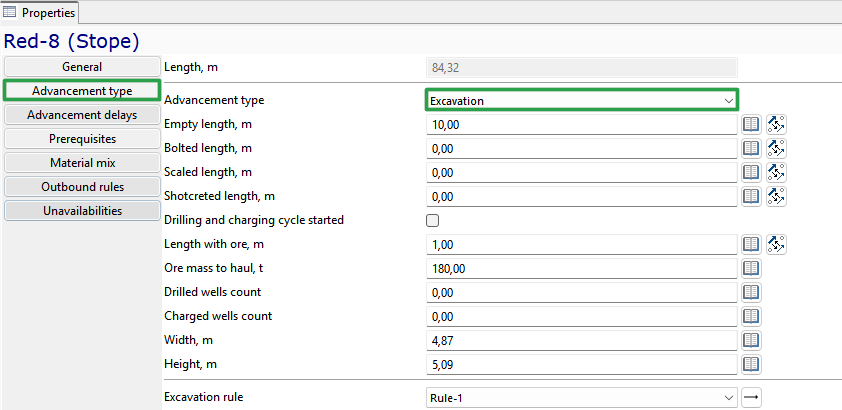
With the Excavation advancement type, the following parameters must be set for the stope:
-
Empty length, m – the length of the stope part where drilling, blasting and transportation of ore have already been fully completed
-
Bolted length, m – the length of the stope part where drilling, blasting and transportation of ore and roof bolting have already been fully completed
-
Scaled length - the length of the part of the mine where drilling, breaking, transporting of the rock mass, and roof sheathing have been completed
-
Drilling and charging cycle started - a parameter that indicates that drilling or charging is started but not yet completed in the stope
-
Do roofbolting - a note about the need for roofbolting
-
Do scaling - a note about the need for scaling
-
Length with ore, m – the length of the stope part where drilling, charging and blasting of the ore mass are completed and the haulage of the ore mass is required
-
Ore mass to haul, t
-
Drilled wells count
-
Charged wells count
-
Number of charged wells
-
Width of the stope, m
-
Height of the stope, m
-
Excavation rule – one of the possible rules containing additional information about the drilling rules (maximum drilling depth, number of wells per m2 face, etc.).
Cleaning
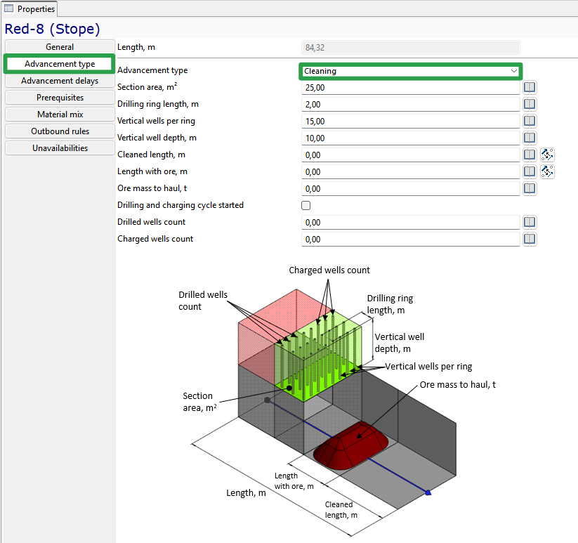
With the Cleaning advancement type, the following parameters must be set for the stope:
-
Section area, m2 – average section area of the stope during cleaning
-
Drilling ring length, m – distance between two drill rings
-
Number of vertical wells per one ring
-
The average depth of a vertical well, m
-
Cleaned length – the length of the stope part where drilling, blasting and transportation of ore have already been fully completed
-
Length with ore, m – the length of the stope part where drilling, charging and blasting of the ore mass are completed and the haulage of the ore mass is required
-
Drilling and charging cycle started - a parameter that indicates that drilling or charging is started but not yet completed in the stope
-
Drilled wells count
-
Charged wells count
Composite
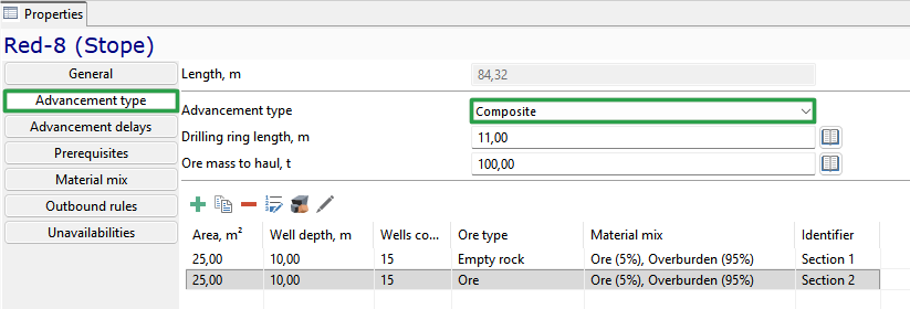
With the Composite advancement type, the following parameters must be set for the stope:
-
Drilling ring length, m – distance between two drill rings
-
Ore mass to haul, t
-
For each drill ring must be set:
-
Section area, m2 – average section area of the stope during cleaning
-
The average depth of a vertical well, m
-
Number of vertical wells
-
Ore type
-
Material mix
-
The button  allows to automatically set the material mix for all drills, corresponding to the materials mix of
the entire stope.
allows to automatically set the material mix for all drills, corresponding to the materials mix of
the entire stope.
The button  allows to automatically set the ore type for all drills, corresponding to the ore type of the entire stope.
The button  allows us to edit the material mix of all drills of the stope in a separate window.
Backfill
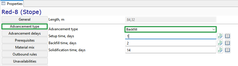
When choosing the test method Backfill, you must fill in the following parameters:
-
Setup time in days
-
Backfill duration in days
-
Solidification time in days
Continuous
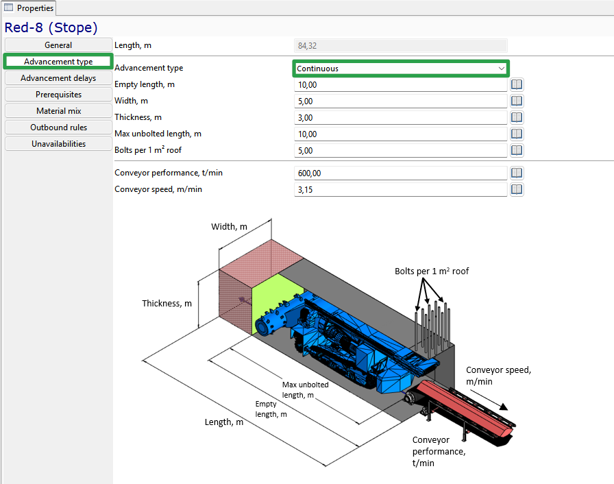
With the Continuous advancement type, the following parameters must be set for the stope:
-
Empty length, m – the length of the stope part where drilling, blasting and transportation of ore have already been fully completed
-
Width of the stope, m
-
Thickness of ore mass cutting by a continuous miner, m
-
Maximum unbolted length, m – the maximum length of the stope on which the continuous miner is allowed to work without strengthening the stope roof
-
Number of bolts per m2 of the stope roof
-
Performance of the conveyor serving the stope, t /min
-
Speed of the conveyor serving the stope, m/min.
Advancement delays
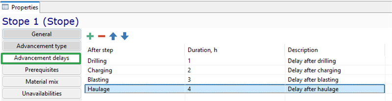
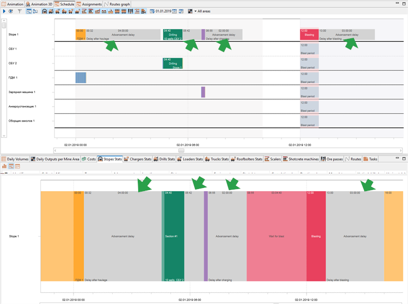
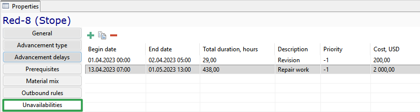
In the block properties on the Advancement delays tab, you can set delays after each stage of stope advancement. This feature is designed for modeling technological pauses before the start of the next stage of work (e.g., ventilation of the stope after blasting).
To create a delay, click the  button, then in the row select the advancement step after which the delay will be added, specify its duration in hours, and add a description that will be displayed on the Gantt chart.
Prerequisites
MineTwin Underground allows us to set prerequisites between stopes, prohibiting the advancement of one stope until the stopes connected to it have been completely advanced.
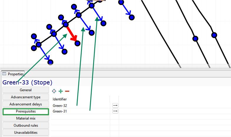
In the figure above, the advancement of Green-33 will be started only after the completion of the Green-32 and Green-31 advancement.
The button  allows you to select on a 2D map and add related stopes; the button
  allows you to add related stopes from the list. The button
  removes related stopes from the list.
Material mix
It is mandatory to fill in the Material mix in the stope.
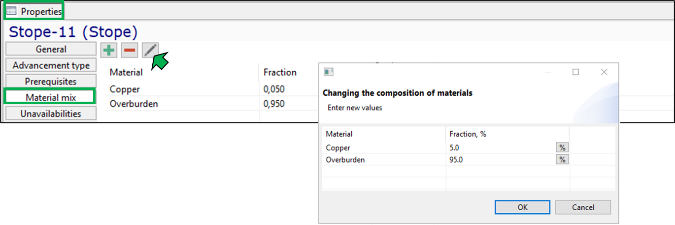
The buttons  allow to add/remove material to stope properties.
The button allows us to edit the material mix in a separate window.
For each material, its proportion in the mix of the ore mass must be specified (from 0 to 1). The total fraction of the material mix should be equal to one.
Outbound rules
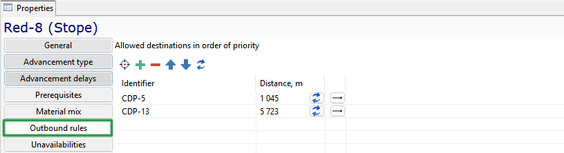
On the Outbound rules tab, you can set a specific set of ore passes and CDPs. The  button allows you to
select export locations on the 2D map, the
button allows you to
select export locations on the 2D map, the  button allows you to add ore passes/overload points from the list,
the
button allows you to add ore passes/overload points from the list,
the  export locations are removed from the list. The
  buttons allow you to swap lines.,
setting the order of testing. The button
buttons allow you to swap lines.,
setting the order of testing. The button  updates the values. The data in this tab is filled in if the function is selected.
Use only allowed destinations on the General tab.
updates the values. The data in this tab is filled in if the function is selected.
Use only allowed destinations on the General tab.
Excavation rule
Excavation rule - an entity that contains the parameters of excavation in underground mines.
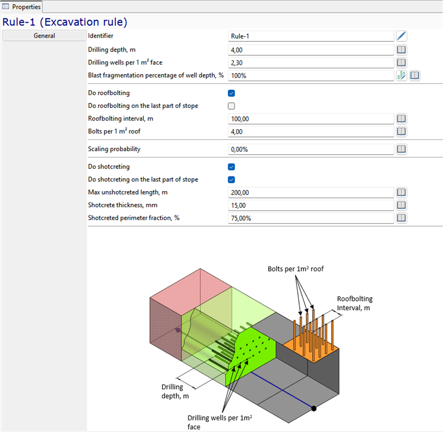
The excavation rule contains the following information about drilling:
-
unique Identifier of the rule
-
Drilling depth in meters
-
Blast fragmentation percentage of well depth, % - percentage of the length of the borehole/well that is separated during blasting
-
Do roofbolting - the function includes the operation of roofbolting with special equipment
-
Do roofbolting on the last part of stope - the parameter allows you to set the support for the entire length of the workings If the checkbox is not selected, the support of the workings is not simulated after the last iteration of drilling and hauling
-
Roofbolting interval, m - maximum length of a workpiece that can be developed without support
-
Bolts per 1 m2 of the stope roof
-
Scaling probability - a parameter that determines the probability of modeling the scaling of the stope after the extraction of the rock mass. If set to 100%, the scaling of the stope will be modeled after each completion of the extraction of the rock mass. If set to 50%, then approximately half of the time, the self-propelled scaler will be modeled after the completion of the extraction, and half of the time, it will not be modeled
-
Do shotcreting - the function includes in the production cycle an additional operation for applying a shotcrete mixture with special equipment. The operation is activated as the production is carried out to a predetermined max unshotcreted length
-
Do shotcreting on the last part of stope - this parameter allows you to set the shotcrete for the entire length of the work. If the mark opposite the parameter is not set, then after the last iteration of the shipment of the blasted rock mass or the roofbolting of the stope, shotcrete is not simulated.
-
Max unshotcreted length, m - the maximum length of the stope, upon reaching which, when carrying out/roofbolting the stope, the shotcrete operation is activated
-
Shotcrete thickness, mm - thickness of the applied layer of shotcrete-concrete mixture
-
Shotcreted perimeter fraction, % - Shotcrete may not be performed over the entire surface of the roof and sides of the stope, but, for example, only the roof or the roof and partially the sides. To determine the shotcrete area, the percentage of the production perimeter to which the mixture is applied is used. If the entire surface needs to be fixed, the parameter should be set to 100%. Then if the height of the work is 5 m, the width is 4 m, and the length without shotcrete is 10 m, then the area of the coating with the mixture will be (2*5+4 )*10=140 m
The element of the tree of objects Excavation rules contains a list of all the rules that can be used in planning and simulation.
Material flow
MineTwin Underground allows us to simulate the movement and processing of ore mass after its excavation from stopes. The mine elements serving the transportation and further processing of the ore mass can be combined into a connected system, the diagram of which is shown in the figure below.

The ore mass goes from the storages to the crushers, processing plants and blenders, and then goes back to the storages for further processing or is transported to dump areas.
Elements of the system of transportation and processing ore mass are combined into a block of the model tree Material flow:
-
Ore passes
-
Storages
-
Skip hoists
-
Crushers
-
Cross-dock points
-
Conveyors
-
Processing plants
-
Railveyor routes
Ore passes
Ore pass - a part of the mine transport system involved in the movement of rock mass from the working area of the mine to the transport horizon.
General
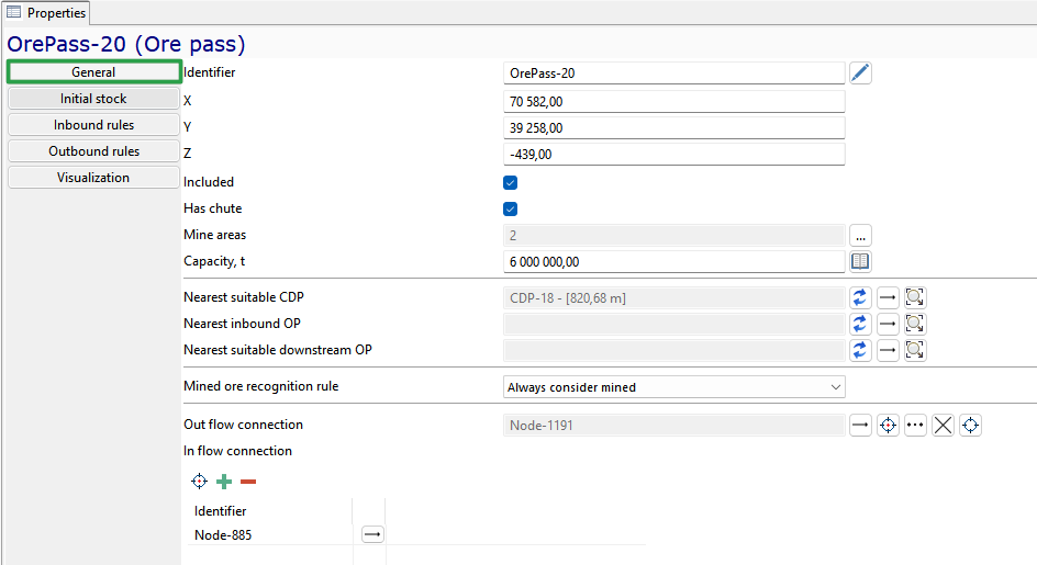
The ore pass is characterized by the following main parameters:
-
unique Identifier
-
X-, Y-and Z-coordinates
-
Included - parameter that indicates whether the equipment unit will be used for scheduling/simulation
-
Has chute - the parameter indicates the method of loading the ore mass in the ore pass. If the ore pass is equipped with a chute, the ore mass is loaded directly into the dump truck without the use of loaders. If the ore pass is not equipped with a chute, the loading of the ore mass in the ore pass involves the use of loaders and one or more dump trucks, into which the loaders load the ore mass.
-
Mine areas - an optional parameter. If a section is specified, only ore mass from stopes with the same section will be transported to the ore pass
-
Capacity, t - the maximum amount of ore mass that a ore pass can hold
-
Max outbound rate, t/min – rate of ore mass discharge from the ore pass to the conveyor
-
Max relative stock to accept transporters, % – determines the level of ore pass filling at which the loader/dump truck stops transporting ore to the current ore pass and begins transporting it to alternative ore pass if any are available
-
Nearest suitable CDP - the nearest overload point with the appropriate ore type is displayed, from which the ore mass can be received
-
Nearest inbound OP - the nearest ore pass with a suitable ore type is displayed, from which the ore pass can receive ore
-
Nearest suitable downstream OP - the nearest ore pass with a suitable ore type that can transport the ore from this ore pass
-
Mined ore recognitions rule - rule for determining when the ore mass should be considered mined for statistics:
-
when the rule is selected Consider mined if no outflow, the ore mass that enters this ore pass will be considered mined only if the ore pass is the final storage location for the ore mass, i.e. it does not have an output node or connection to a conveyor, crusher, etc.
-
when the rule is selected Always consider mined, the ore mass that enters this ore pass will always be considered mined
-
If the rule is Never consider mined, the ore mass that enters the ore pass will never be considered mined (because it must be accounted for at a later stage of movement through the mine).
-
-
Output connection is a reference to a transport network or equipment node where the ore is loaded from the ore pass. The ore can be loaded into the ore pass at multiple nodes in the mine field, including those located at different depths.
-
The Input connection field contains a list of transport network nodes where vehicles can unload the ore into the ore pass.
The  button allows you to select the desired minefield nodes on the 2D map, and the
  button
allows you to add nodes from the list. The
button
allows you to add nodes from the list. The  button removes minefield nodes from the list.
Initial stock
The Initial stock tab sets the characteristics of the rock mass in the ore pass at the beginning of the planning process. If the ore pass is empty at the beginning of the planning process, you do not need to fill in the tab.
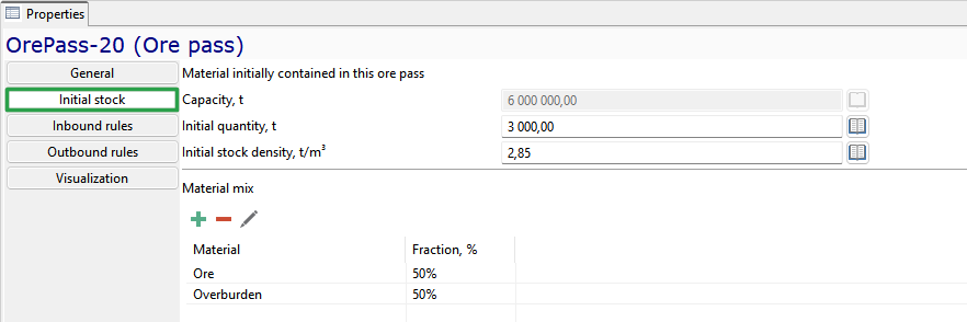
If the ore pass contains a mass of ore at the beginning of the simulation, the tab displays:
-
Initial quantity, t - in the ore pass
-
Initial density, t/m3 - density of the ore mass in the ore pass
-
Material mix - the percentage of rocks/ore in the initial reserve
The  button allows you to add rows to fill in the rock mass type.
The
button allows you to add rows to fill in the rock mass type.
The  button removes entries from the list. The
  button opens a window for filling in the rock composition at the beginning of the simulation.
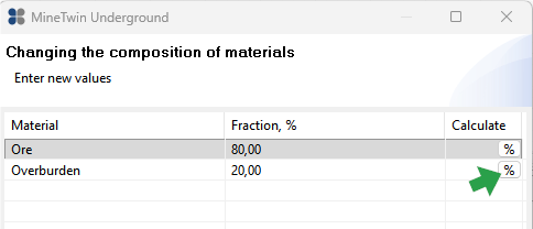
If the cross-dock point is empty at the beginning of the planning process, the Initial stock tab is not filled in.
Inbound rules
The Inbound rules tab sets restrictions on the acceptance of ore into the ore pass.
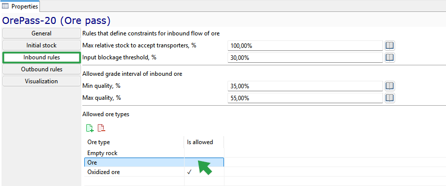
-
Maximum relative stock to accept transportrs, % - determines the level of ore pass filling at which the truck/loader stops transporting ore to the given ore pass and starts transporting it to alternative ore passes, if any
-
Input blockage threshold, %. For example, the ore pass is filled to its maximum capacity of 10,000 tons, and the conveyor that transports the ore to the ore pass stops (locks). The ore then flows to the crusher. The conveyor will only resume operation when the amount of ore in the ore pass reaches a specified level, such as 30%, which means that only 3,000 tons of ore remain in the ore pass.
-
Allowed grade interval of inbound ore:
-
Minimum grade, % - minimum quality of rock mass that can be hauled to this ore pass
-
Maximum grade, % - maximum quality of rock mass that can be hauled to this ore pass
-
-
Allowed ore types - in the Is allowed column, a mark must be placed next to the type of mining mass that the dumpf area can inbound
The buttons  allow to select all ore types / remove all selections.
Outbound rules
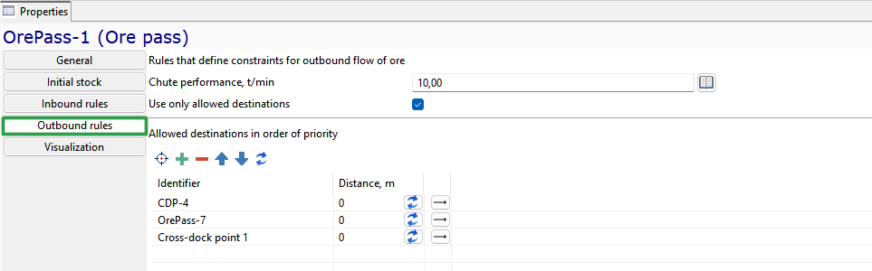
The Outbound rules tab sets the parameters for unloading and further transportation of the ore from the ore pass.
-
Chute perfomance, t/min – ore unloading performance
-
Use only allowed destination - when this function is enabled, the ore mass from the ore pass will be transported only to the ore passes specified in the Allowed destination in order of priority table
-
The table below lists the Allowed destinations in order of priority – ore pass and/or cross-dock points (the top entry is the highest priority, and the bottom row is the lowest priority)
The  button allows you to select the desired collection locations on the 2D map, while the
  button allows you to add objects from the list.
The
button allows you to add objects from the list.
The  button removes entries from the list. The
  button allows you to go to the properties of the selected object. The
  button allows you to update the distance data to the corresponding objects.
Storage
Storage - a place for intermediate storage of ore mass.
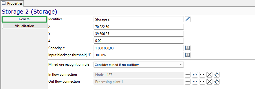
The storage is characterized by the following properties:
-
unique Identifier
-
X-, Y- and Z-coordinates
-
Capasity, t - the maximum quantity of ore that can accommodate the storage
-
Input blockage threshold, % - the level of fullness for resuming the operation of the element of the in-line transport technology included in it, %. For example, the storage is filled to the maximum capacity of 10,000t, and the conveyor transporting the rock mass into it stops (is blocked). From the storage, the rock mass enters the crusher. The conveyor will resume its operation only when the amount of rock mass in the storage drops to a given level, for example, 30%, i.e. when only 3,000t remains in the storage.
-
In flow connector - reference to the equipment unit from which the ore mass enters the storage: crusher, conveyor, processing plant, or skip hoist
-
Outflow connector - a reference to the equipment unit to which the ore mass enters from the storage: rusher, processing plant, or skip hoist
-
Mined ore recognitions rule - rule for determining when the rock mass should be considered mined for statistics:
-
when the rule is selected Consider mined if no outflow, The rock mass that enters this storage facility will be considered mined only if the storage facility is the final location for the rock mass, i.e., it does not have an output connection to a conveyor, crusher, etc.
-
when the rule is selected Always consider mined, the rock mass that enters this storage will always be considered mined
-
If the rule is Never consider mined, the rock mass that enters the storage will never be considered mined (because it must be accounted for at a later stage of movement through the mine).
-
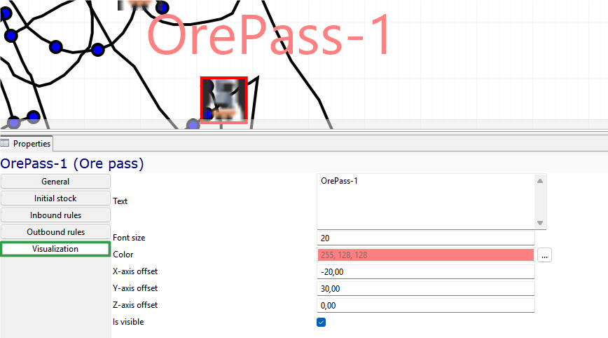
In the Text label tab, you can customize the display of the object’s text label.
Skip hoist
Skip hoist - a piece of equipment designed to lift the ore mass from an underground mine to the surface of the earth.
General
A skip hoist consists of a pair of skip trolleys (skips). In the process of lifting the ore mass, the ore is alternately loaded into one skip and transported to the top. While one skip is being raised, the other skip is lowered.
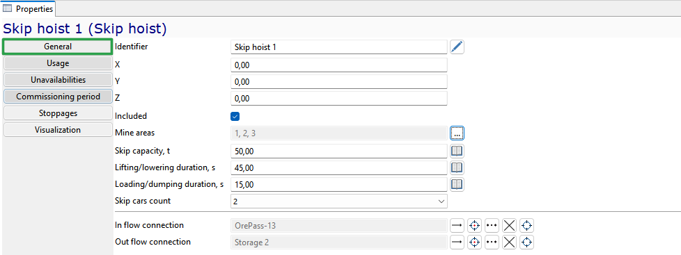
The skip hoist is characterized by the following main parameters:
-
unique Identifier
-
X-, Y- and Z-coordinates
-
Included - parameter that indicates whether the equipment unit will be used for scheduling/simulation
-
Mine area to which the equipment unit is assigned
-
Scip capacity, t – capacity of skip trolley in tones
-
Lifting/lowering duration, s - the duration of lifting and lowering of skip trolley (as the processes of lifting one skip and lowering the other occur in parallel, the duration of these cycles is the same), in seconds
-
Loading/dumping duration, s - the duration of loading and unloading of one skip trolley (as the processes of loading one skip and unloading another occur in parallel, the duration of these cycles is the same), in seconds
-
Skip cars count: one or two
-
In flow connector - reference to the ore pass from which the ore mass enters the skip hoist
-
Outflow connector - reference to the storage to which the ore mass enters from the skip hoist
Usage
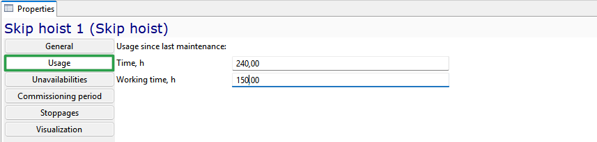
On the Usage tab, you can set the initial state of parameters related to equipment maintenance, depending on the calendar time or operating hours since the last maintenance:
-
Time – the number of hours since the last maintenance or repair. The parameter is used when determining the maintenance frequency based on the Time parameter, which is set in the Maintenance group.
-
Working time – the number of motor hours (hours of motor operation during movement, loading, and unloading) that the equipment unit has worked at the start of planning/simulation. The parameter is used when determining the maintenance frequency based on the Working time parameter, which is set in the Maintenance group.
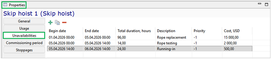
Unavailabilities
For equipment in the Material flow group, you can also set planned periods of inaccessibility on the Unavailabilities tab.
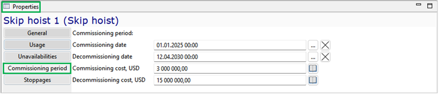
Comissioning period
In the Comissioning period tab, the dates of commissioning and decommissioning of the equipment unit can be set, as well as the costs of commissioning (purchase) and decommissioning (disposal). Before the date of commissioning / after the date of decommissioning, the equipment unit is not included in the planning/simulation.
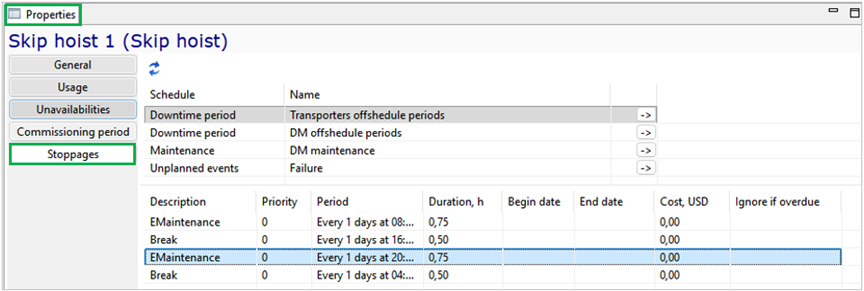
Stoppages
The Stoppages tab is used to view the list of scheduled and random downtime events specified in the Schedule object tree group.
In the Text label tab, you can customize the display of the object’s text label.
Crusher
Crusher - a piece of equipment for crushing – using mechanical impact on the rock to destroy it.
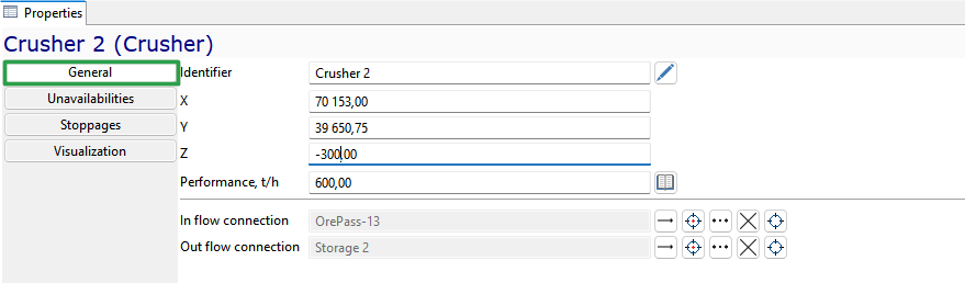
The crusher is characterized by the following main parameters:
-
unique Identifier
-
X-, Y- and Z-coordinates
-
Performance, t/h
-
In flow connector - reference to the equipment unit from which the ore mass enters the crusher: storage or conveyor
-
Out flow connector - reference to the equipment unit to which the ore mass enters from the crusher: storage, conveyor or processing plant.
You can set periods of Unavailability for the crusher. The Stoppages tab provides information about all planned and probabilistic downtime periods, with a button that allows you to navigate to the corresponding editing window in the Schedules group. In the Text label tab, you can customize the display of the object’s text label.
Cross-dock point
Cross-dock point - a mine node where equipment stops while waiting for loaders and trucks, and the ore mass is reloaded from loaders to trucks.
General
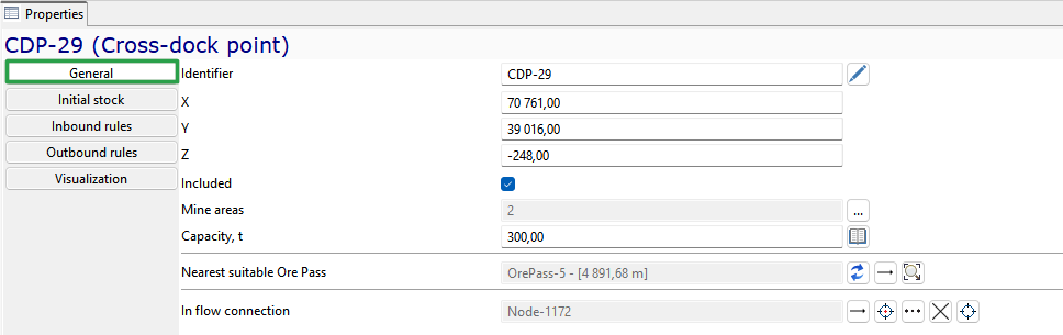
The cross-dock point is characterized by the following General parameters:
-
unique Identifier
-
X-, Y-and Z-coordinates
-
Included - parameter that indicates whether the equipment unit will be used for scheduling/simulation
-
Mine areas to which the equipment unit is assigned
-
Capasity, t - the maximum amount of rock mass that a cross-dock point can hold
-
Nearest suitable ore pass - the closest ore pass to the cross-dock point that can take on the ore type of the cross-dock point. The nearest suitable ore pass is determined automatically
-
In flow connection - link to the transport network node from which the download will be performed
Initial stock
The Initial stock tab fills in the characteristics of the ore mass that is at the cross-dock point at the beginning of the model period.
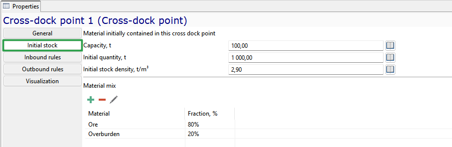
The tab displays the total capacity of the cross-dock point in tons, as well as data that is filled in when the volume of ore mass at the transfer point is available at the start of planning:
-
Initial quantity, t - amount of ore mass in the cross-dock point
-
Initial stock density, t/m3, in the cross-dock point
-
Material mix - the percentage of rocks/ore in the initial reserve
The button allows you to add rows to fill in the rock mass type.
The button removes entries from the list. The button opens a window for filling in the rock composition at the beginning of the simulation.
If the cross-dock point is empty at the beginning of the planning process, the Initial stock tab is not filled in.
Inbound rules
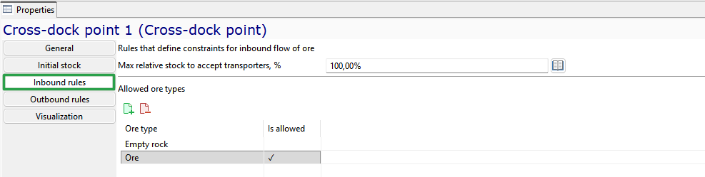
The Inbound rules tab sets restrictions on the acceptance of ore mass at the cross-dock point.
-
Max relative stock to accept transporters, % – determines the level of ore cross-dock point filling at which the loader/dump truck stops transporting ore to the current cross-dock point and begins transporting it to alternative cross-dock point if any are available
-
Allowed ore types - selected manually by checking the box next to the required type of ore mass.
The buttons allow to select all ore types / remove all selections.
Outbound rules
The Outbound rules tab sets the parameters for unloading and further transportation of the ore from the cross-dock point.
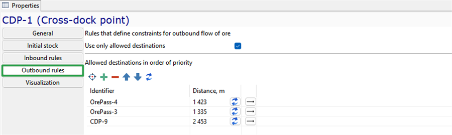
-
Use only allowed destination - when this function is enabled, the ore mass from the cross-dock point will be transported only to the cross-dock pointes specified in the Allowed destination in order of priority table
-
The table below lists the Allowed destinations in order of priority – ore pass and/or cross-dock points (the top entry is the highest priority, and the bottom row is the lowest priority)
The button allows you to select the desired collection locations on the 2D map, while the button allows you to add objects from the list.
The button removes entries from the list. The button allows you to go to the properties of the selected object. The button allows you to update the distance data to the corresponding objects.
In the Text label tab, you can customize the display of the object’s text label.
Conveyor
Conveyor - a continuous-action mechanism for transporting ore mass. The ore mass can enter the conveyor from storages, crushers and processing plants and is transported to storages, crushers and processing plants.
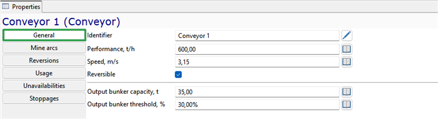
The conveyor is characterized by the following main parameters:
-
unique Identifier
-
Performance of ore mass transportation in tons per minute
-
Conveyor belt speed, m/min
-
Reversible - setting a mark next to the parameter enables the tape to move in the opposite direction. The schedule of the periods is set on the Reversions
-
Output bunker capacity, t - is a technical parameter that is used to prevent the simulation from stopping with an error. In reality, an overflow conveyor is an emergency situation. In the simulation, the excess rock mass enters the internal virtual buffer, and after it fills up to the set value, the conveyor will stop (block). This can happen if the rock mass enters one conveyor from several conveyors, or if the underlying conveyor stops for a break or breakdown.
-
Output bunker threshold, % - is the percentage of occupancy of the internal buffer at which the conveyor resumes operation after an emergency stop.
Mine arcs
One conveyor can consist of several arcs. In the Mine arcs tab, you can set the list of mine arcs of the conveyor that make up the given conveyor.
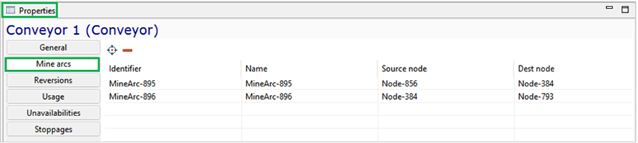
Mine arcs are added by selecting them on the minefield using the button and removed from the conveyor using the
button .
Reversions
The Reversions tab sets the periods of time when the conveyor operates in reverse mode (in the opposite direction).
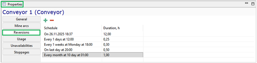
In the conveyor properties, the initial Usage and periods of Unavailability can be set in the corresponding tabs. The Stoppages tab provides information about all planned and probabilistic downtime periods, with a button that allows you to navigate to the corresponding editing window in the Schedules group.
Processing plant
Processing plant - a mining enterprise for the primary processing of ore mass to obtain technically valuable products suitable for industrial use.
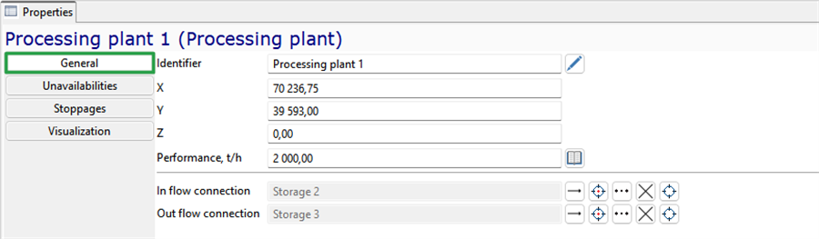
The processing plant is characterized by the following General parameters:
-
unique Identifier
-
X-, Y- and Z-coordinates
-
Performance of ore mass processing in tons per hour
-
In flow connector - reference to the equipment unit from which the ore mass enters the processing plant: crusher, storage or conveyor
-
Outflow connector - reference to the equipment unit to which the ore mass enters from the processing plant: storage or conveyor.
You can set periods of Unavailability for the processing plant. The Stoppages tab provides information about all planned and probabilistic downtime periods, with a button that allows you to navigate to the corresponding editing window in the Schedules group. In the Text label tab, you can customize the display of the object’s text label.
Railveyor route
The Railveyor route route defines a sequence of ore passes along the railway conveyor’s path. The routes are fixed and contain a sequence of ore passes that the railway conveyor will unload.
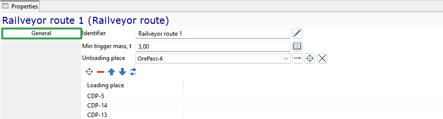
The route of the railway conveyors is characterized by the following parameters:
-
unique Identifier
-
*Minimum trigger mass in the ore pass for the start of its removal by the railway conveyor
-
Unloading place – a link to the storage facility where the rock mass will be unloaded from the railway conveyor following this route
-
Loading place – a list of ore passes from which the railway conveyor will load ore in the specified order during its movement along the route. Ore passes are added to the route by selecting them on the mine field using the button
, and removed using the button . The order of the ore passes in the route can be changed using the arrows, and the route can be updated
using the button .
Parameters of mobile equipment
Mobile equipment in MineTwin Underground is grouped by type. Equipment type is an entity used to group equipment units with the same basic characteristics.
The Equipment types object tree element contains lists of all equipment types that can be used for scheduling/simulation:
-
Truck types
-
Loader types
-
Charger types
-
Drilling machine types
-
Roofbolter types
-
Shotcrete machine types
-
Shuttle car types
-
Continuous miner types
-
Scaler types
Scheduled repairs (maintenance sets), Scheduled and unscheduled (emergency) repairs sets (unplanned events) are specified in the context of equipment types.
For equipment types, the parameter Bypassing enable in passing manoeuvres is specified, which determines whether equipment of this type takes part in passing manoeuvres when travelling along roads for which such manoeuvres are required (mine arcs of the Road type with the Opposite moving allowed, and Moving overtaking allowed and Stopped overtaking allowed functions enabled. When traveling on the same arc, equipment passes according to the following rules:
-
If two units are moving in opposite directions, the second one waits at a mine node until the first completes its travel along the arc
-
If two units are moving in the same direction, they cannot overtake each other on the arc; overtaking is only possible at a node
-
If a piece of equipment has stopped on a road section, the second piece will require additional time to go around it. If a piece of equipment has stopped on an edge with the Overtaking stopped equipment function disabled, then the equipment participating in passing manoeuvres will stop before this edge and wait until the road is clear.
Additionally, maintenance costs for equipment types are specified at the equipment type level. On the Cost tab, the following cost parameters can be filled in for all equipment types:
-
Monthly fixed cost, USD
-
Cost per active shift, USD
-
Cost per working hour, USD
-
Cost per 1 kilometer traveled, USD.
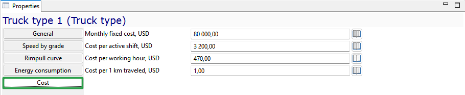
Filling in these parameters is optional and is used when estimating operational expenditures during the simulation.
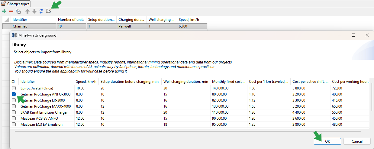
MineTwin Underground contains the built-in library for commonly used equipment types. You can create an equipment type by going to the equipment library and selecting the required types of equipment and then tune it to match your equipment type.
Truck types
Truck - a machine designed for loading and transporting ore mass.
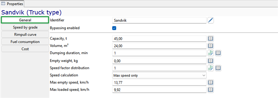
The following properties have to be set for each truck type on the General tab:
-
Unique identifier
-
Bypassing enabled - if checked, the equipment unit of this type will participate in bypassing maneuvers when traveling along the arcs that require vehicle bypassing
-
Capacity, t - capacity of trucks of this type in metric tons
-
Volume, m3 - the maximum quantity of ore that the truck of this type can haul in m3
-
Dumping duration, min
-
Spotting at loading duration, min - the duration of spotting operations when positioning for loading. During the spotting at loading time, the loader can either wait for the spotting to complete and only then start loading the truck, or begin the loading process in parallel with spotting – for example, scooping ore into the bucket. The choice of option is set directly in the properties of the loader types
-
Spotting at dumping duration, min - the duration of spotting operations before dumping
-
Empty weight, kg - empty truck weight in kilograms. This parameter is used in rimpull calculations
-
Speed factor distribution - this parameter allows you to introduce variability of speed in the defined range. Parameter can be a constant or a random variable with one of the built-in distributions. The calculated speed of the vehicle will be multiplied by this parameter, and in the case of random variable the speed will be variable.
-
Speed calculation - one of three options for calculating the speed of rock mass haulage equipment:
-
Using only the maximum speed of this equipment type. In this case, travel speed will depend solely on road quality
-
Speed calculation accounting for road gradient. In this case, simulation uses linear interpolation of a tabular speed function defined on the Speed by grade tab. If the defined maximum speeds are lower than those in the table, the maximum speeds will be used. The speed calculated based on gradient is also adjusted by the road quality coefficient
-
Speed calculation accounting for rolling resistance, which occurs when wheeled equipment tires roll on the road surface. In this case, a function of vehicle speed versus the force it exerts on the road is used. This function is defined on the Rimpull curve tab. The speed obtained by any of these rules is adjusted for road quality. On all arcs with a road quality of 1, the speed will equal the calculated value. On arcs where road quality is not 1, the speed will be adjusted by the specified coefficient. The speed factor distribution is also applied to the calculated speed.
-
-
Max empty speed, km/h - absolute maximum speed of moving empty. Note that the actual speed may depend on rimpull curve data, angle-based speed settings and road quality. But the resulting speed of moving empty can never be greater than this value
-
Max loaded speed, km/h - absolute maximum speed of moving loaded. Note that the actual speed may depend on rimpull curve data, angle-based speed settings and road quality. But the resulting speed of moving loaded can never be greater than this value
Speed by grade
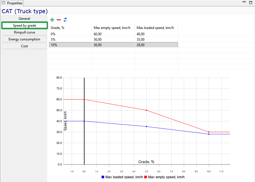
On the Speed by grade tab, the speed characteristics of haul truck types are defined as a function of road gradient angle. For each range of angles, the corresponding travel speeds with and without load are indicated. Intermediate values are determined by linear interpolation and are displayed on the graph.
Acceleration
On the Acceleration tab, you can enable acceleration and deceleration simulation. The Acceleration rule parameter provides the following options:
-
Do not simulate — acceleration is not simulated
-
Constant max acceleration — the equipment speed increases every second by the specified Max acceleration value
-
Rimpull curve based — acceleration is recalculated every second based on the equipment’s current speed and the force acting along the road, using the rimpull curve.
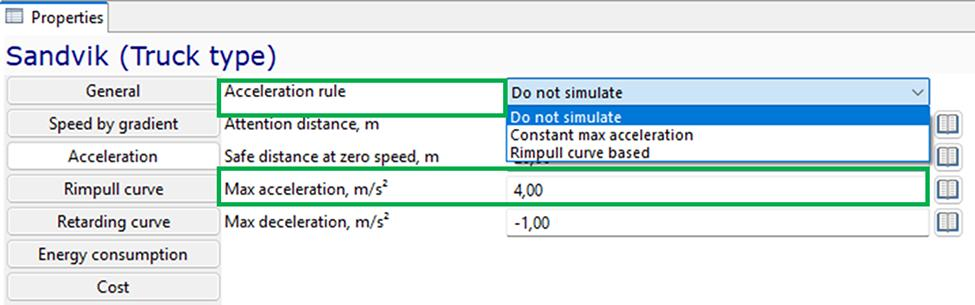
The following parameters are also specified on this tab:
-
Attention distance, m — the distance at which the equipment detects an obstacle
-
Safe distance at zero speed, m — the minimum distance that must remain between the equipment and an obstacle if the latter stops suddenly
-
Max acceleration, m/s2 — the maximum speed increase per second when the Constant max acceleration rule is selected
-
Max deceleration, m/s2 — the maximum allowable speed reduction, which determines the minimum braking distance.
When constant maximum acceleration is used, the equipment accelerates by the specified value every second until it reaches the maximum speed determined by the selected speed calculation method: maximum values, speed by gradient, or the rimpull curve.
Acceleration is simulated:
-
When the equipment starts moving
-
When an object that was limiting its speed clears its path.
Deceleration is simulated:
-
When the equipment approaches its destination
-
When it approaches slower-moving equipment on a road where overtaking is not permitted
-
When it approaches an intersection where another vehicle may obstruct its movement.
Only equipment that participates in traffic interaction is treated as an obstacle when acceleration and deceleration are calculated.
Rimpull curve
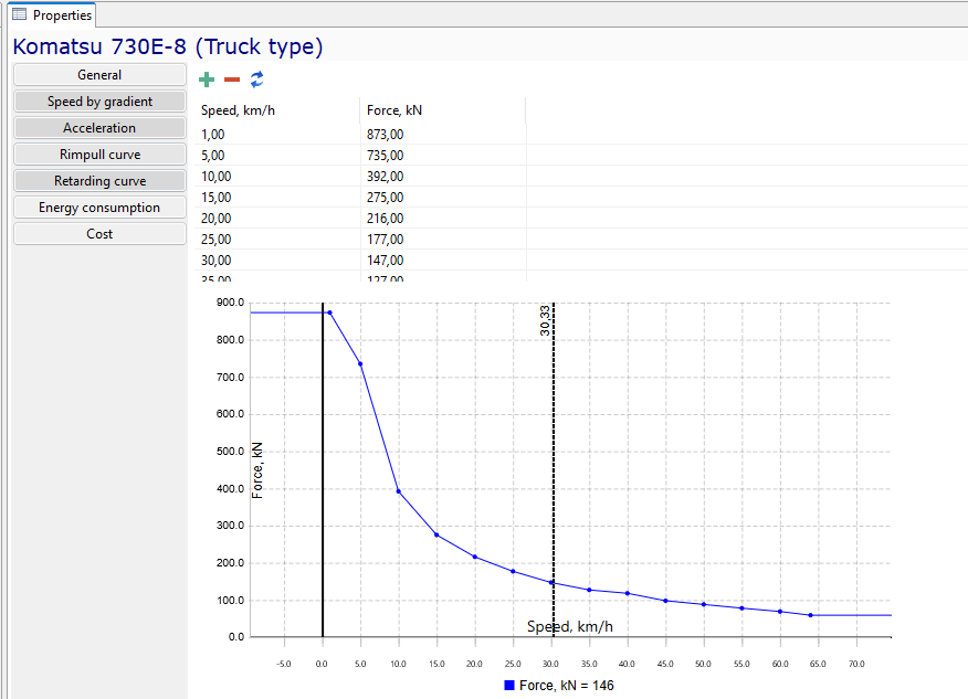
On the Rimpull curve tab, values describing the relationship between tractive effort (the tractive force available at the wheels) and the travel speed of a haul truck of this type can be specified. Intermediate values are determined by linear interpolation and are displayed on the graph. The rimpull curve is used only when Rimpull curve based is selected as the speed calculation method.
Retarding curve
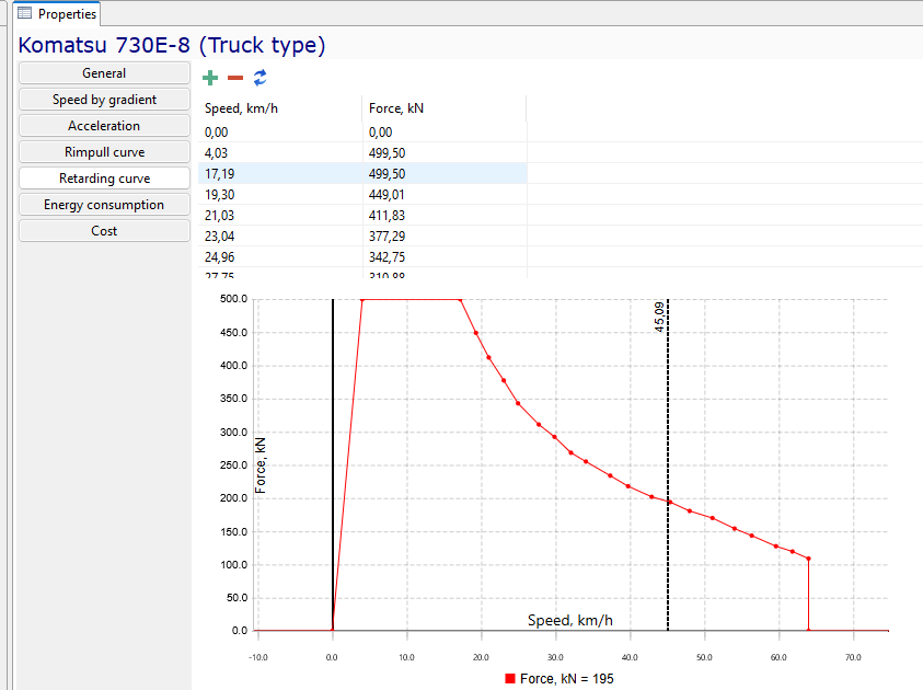
The retarding curve determines the maximum speed at which the equipment can travel downhill while allowing the retarder or braking system to maintain that speed without overheating.
The curve does not describe braking dynamics. It is used only as an additional speed limit on downhill road segments and is not applied on level roads or uphill segments.
The retarding curve is used only when Rimpull curve based is selected as the speed calculation method. The resulting speed is also adjusted by the road quality coefficient and the Speed factor distribution.
Energy consumption
On the Energy Consumption tab, one of three available energy source options must be selected: Fuel, Fixed battery, or Swappable battery. After selecting the energy source, the corresponding energy consumption parameters must be filled in.
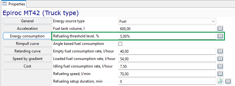
When Fuel is selected as the energy source, the following values are specified:
-
Fuel tank capacity, liters
-
Fuel tank volum, liters
-
Refueling threshold level, % — the fuel level at which the equipment unit starts travelling to a fueling station
-
Angle based fuel consumption — if this checkbox is selected, fuel consumption for haul trucks of this type is calculated based on fuel consumption curves vs. road gradient; otherwise, a constant consumption rate is used for various states (loaded, empty, idling). The dependencies are entered in tabular form for travel with load and without load. Road gradient is specified as a percentage, and the curves on the chart are generated automatically
-
Empty fuel consumption rate, l/hour — constant consumption rate when travelling without load, used if the effect of road gradient does not need to be taken into account
-
Loaded fuel consumption rate, l/hour — constant consumption rate when travelling with load, used if the effect of road gradient does not need to be taken into account
-
Idling fuel consumption rate, l/hour — constant consumption rate when the haul truck is not in motion
-
Fueling rate, l/min — the refuelling rate for haul trucks of this type
-
Fueling preparation time, min — the delay required to prepare haul trucks of this type before refuelling begins. This may be specified as either a constant or a random variable.
When Fixed battery is selected as the energy source, the following values are specified:
-
Empty power consumption rate, kW
-
Loaded power consumption rate, kW
-
Idling power consumption rate, kW
-
Recharding preparation duration, min — the delay before charging begins. This may be specified as either a constant or a random variable
-
Battery type — selection of a battery type from the list available in the scenario.
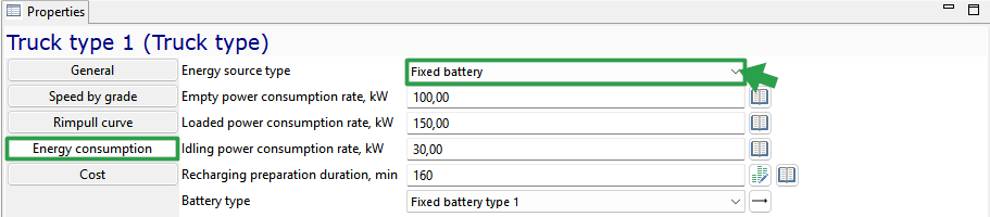
When Swappaable battery is selected as the energy source, the following values are specified:
-
Empty power consumption rate, kW
-
Loaded power consumption rate, kW
-
Idling power consumption rate, kW
-
Battery mount duration, min — the delay before charging begins. This may be specified as either a constant or a random variable
-
Battery dismount duration — selection of a battery type from the list available in the scenario.
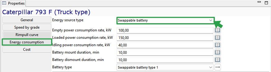
Loader types
Loader - a machine designed for loading and transporting ore mass to the dump area.
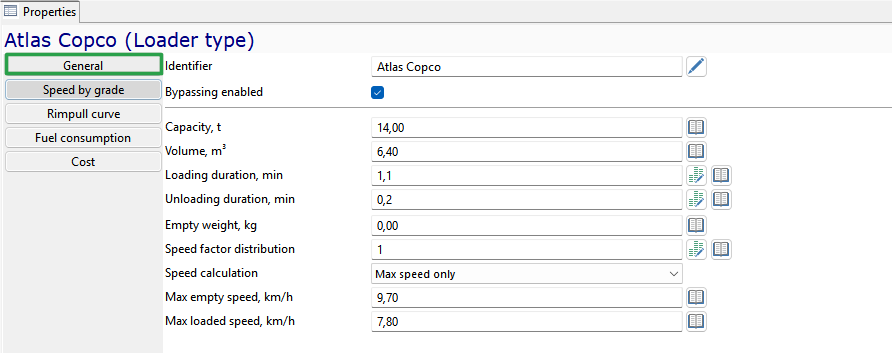
The following properties have to be set for each loader type on the General tab:
-
Unique identifier
-
Bypassing enabled - if checked, the equipment unit of this type will participate in bypassing maneuvers when traveling along the arcs that require vehicle bypassing.
-
Capacity, t - carrying bucket of loaders of this type in tons
-
Volume, m3 - the maximum quantity of ore that can be placed in the load-carrying bucket of loaders of this type in m3
-
Bucket loading duration, min
-
Bucket unloading duration, min
-
Start loading truck – a parameter that determines whether an loader of this type will be engaged in productive work while the haul truck is spotting for loading. The parameter is set by selecting an option from the list:
-
After truck spotting is complete – means that the loader will start the loading process after the haul truck has finished spotting into loading position
-
At the start of truck spotting – means that while the haul truck is spotting for loading, the loader is engaged in productive work
-
-
Empty weight, kg - empty loader weight in kilograms. This parameter is used in rimpull calculations
-
Speed factor distribution - this parameter allows you to introduce variability of speed in the defined range. Parameter can be a constant or a random variable with one of the built-in distributions. The calculated speed of the vehicle will be multiplied by this parameter, and in the case of random variable the speed will be variable.
-
Speed calculation - one of three options for calculating the speed of rock mass haulage equipment:
-
Using only the maximum speed of this equipment type. In this case, travel speed will depend solely on road quality
-
Speed calculation accounting for road gradient. In this case, simulation uses linear interpolation of a tabular speed function defined on the Speed by grade tab. If the defined maximum speeds are lower than those in the table, the maximum speeds will be used. The speed calculated based on gradient is also adjusted by the road quality coefficient
-
Speed calculation accounting for rolling resistance, which occurs when wheeled equipment tires roll on the road surface. In this case, a function of vehicle speed versus the force it exerts on the road is used. This function is defined on the Rimpull curve tab. The speed obtained by any of these rules is adjusted for road quality. On all arcs with a road quality of 1, the speed will equal the calculated value. On arcs where road quality is not 1, the speed will be adjusted by the specified coefficient. The speed factor distribution is also applied to the calculated speed.
-
-
Max empty speed, km/h - absolute maximum speed of moving empty. Note that the actual speed may depend on rimpull curve data, angle-based speed settings and road quality. But the resulting speed of moving empty can never be greater than this value
-
Max loaded speed, km/h - absolute maximum speed of moving loaded. Note that the actual speed may depend on rimpull curve data, angle-based speed settings and road quality. But the resulting speed of moving loaded can never be greater than this value
Similarly to truck types, on the Speed by grade tab, the speed characteristics of LHD equipment types are defined as a function of road gradient angle. On the Acceleration tab, you can specify the acceleration and deceleration parameters and the minimum safe distance from an obstacle. On the Rimpull curve and Retarding curve tabs, you can specify the relationships between tractive or retarding effort and the travel speed of an LHD of this type. On the Energy consumption tab, the energy source type and its consumption parameters are specified. As with haul trucks, one of the following options is available: Fuel, Fixed battery or _Swappable battery. On the Cost tab, the costs for maintenance and servicing of equipment of this type are entered.
Charger types
Charger - a device for the mechanized feeding of explosive material (EM) to charging planes (wells, blast holes).
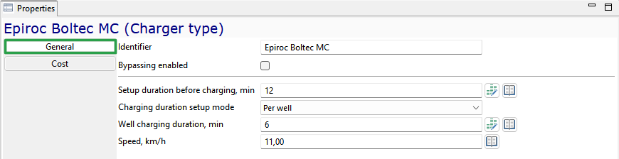
The following basic properties must be set for each charger type:
-
Unique Identifier
-
Bypassing enabled - if checked, the equipment unit of this type will participate in bypassing maneuvers when traveling along the arcs that require vehicle bypassing
-
Setup duration before charging, min
-
Charging duration setup mode - one of two possible methods for accounting for the time to charge blast holes/wells with explosive material: Time per blast hole/well or Time per meter of hole/well depth
-
Well chargigng duration, min
-
Speed, km/h - constant travel speed of this type of chargers
The setup and charging duration can be set by a constant value or by one of the distributions.
On the Cost tab, the costs for maintenance and servicing of equipment of this type are entered.
Drilling machine types
Drilling machine - a piece of equipment designed for drilling wells/ holes, capable of independently moving around an open-pit mine.
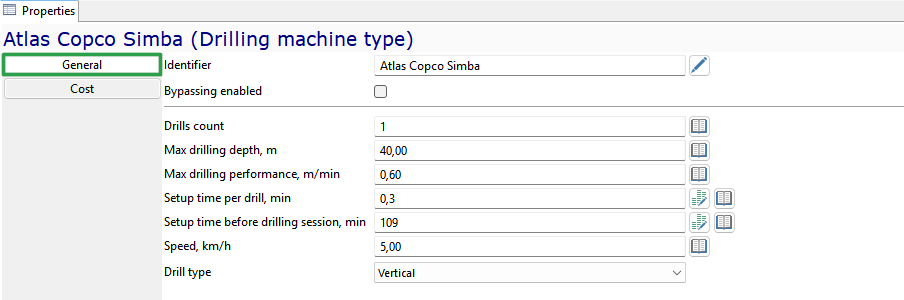
On General tab you can set the following properties for each drilling machine type:
-
Unique Identifier
-
Bypassing enabled - if checked, the equipment unit of this type will participate in bypassing maneuvers when traveling along the arcs that require vehicle bypassing
-
Drills count - the number of drilling tools. As a rule, a horizontal drilling machine has 2 booms, a vertical drilling machine has 1 boom
-
Max drilling depth, m possible for this type of drilling machine
-
Max drilling performance, m/min
-
Setup time per drill, min - duration of preparatory work, such as installing the drilling machine, connecting electricity and water, etc.
-
Setup time before drilling session, min - duration of manipulations before drilling each well/hole
-
Constant speed of this type of drilling machines in km/h.
On the Cost tab, the costs for maintenance and servicing of equipment of this type are entered.
Roofbolter types
Roof bolter - equipment designed for installation of roof bolting during mining operations.
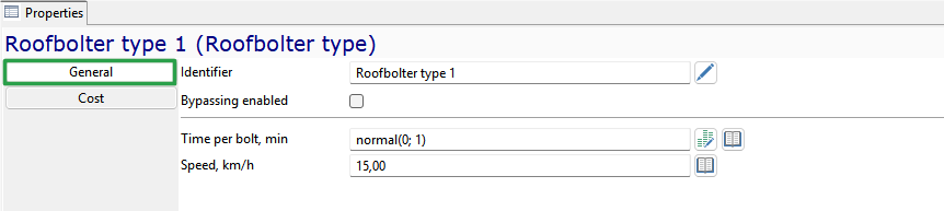
On General tab you can set the following properties for each roofbolter type:
-
Unique Identifier
-
Bypassing enabled - if checked, the equipment unit of this type will participate in bypassing maneuvers when traveling along the arcs that require vehicle bypassing
-
Time per bolt, min
-
Speed, km/h - average moving speed of this type of roofbolters in km/h.
The time per bolt can be set as a constant or as a random variable with one of the supported distributions.
On the tab Cost you can fill the cost of operating this type of equipment (but not necessarily).
Shotcrete machine types
A shotcrete machine is a self-propelled equipment for applying special construction mixtures to surfaces under the pressure of compressed air or water. Shotcreting of mine surfaces can be performed for additional reinforcement, waterproofing, or fire protection purposes.
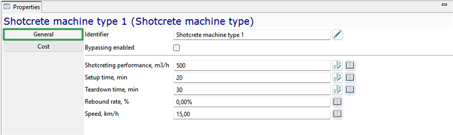
The following general properties are set for each type of shotcrete machine:
-
Unique Identifier
-
Bypassing enabled - if checked, the equipment unit of this type will participate in bypassing maneuvers when traveling along the arcs that require vehicle bypassing
-
Shotcreting perfomance, m3/h - hourly consumption of shotcrete concrete mixture when applied to the surface
-
Setup time, min - total time for surface preparation, dusting, etc. before the spraying process begins
-
Teardown time, min - total time for equipment washing, rebound cleaning, quality control and other operations after the shotcreting process ends before the shotcret machine begins to move
-
Rebound rate, % - percentage of the shotcrete mixture that does not adhere to the surface being treated during application
-
Speed, km/h - speed of movement of the shotcrete machine
On the tab Cost you can fill the cost of operating this type of equipment (but not necessarily).
Shuttle car types
Shuttle car - equipment containing a bottom conveyor and designed for transporting ore mass in underground mines when working with continuous miners. The continuous miners load the ore mass into shuttle cars, which transfer it to the mine conveyors.
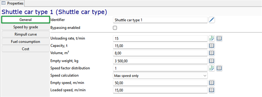
The following properties must be set for each shuttle car type:
-
Unique identifier
-
Bypassing enabled - if checked, the equipment unit of this type will participate in bypassing maneuvers when traveling along the arcs that require vehicle bypassing.
-
Unloading rate — performance of ore mass unloading in tons per minute
-
Capacity of shuttle cars of this type in tons
-
Volume, m3 - the maximum quantity of ore that can be placed in shuttle cars of this type in m3
-
Empty weight, kg - empty shuttle car weight in kilograms
-
Speed factor distribution - this parameter allows you to introduce variability of speed in the defined range. Parameter can be a constant or a random variable with one of the built-in distributions. The calculated speed of the vehicle will be multiplied by this parameter, and in the case of random variable the speed will be variable.
-
Speed calculation - one of two options for calculating the speed of rock mass haulage equipment:
-
Using only the maximum speed of this equipment type. In this case, travel speed will depend solely on road quality
-
Speed calculation accounting for road gradient. In this case, simulation uses linear interpolation of a tabular speed function defined on the Speed by grade tab. If the defined maximum speeds are lower than those in the table, the maximum speeds will be used. The speed calculated based on gradient is also adjusted by the road quality coefficient The speed obtained by any of these rules is adjusted for road quality. On all arcs with a road quality of 1, the speed will equal the calculated value. On arcs where road quality is not 1, the speed will be adjusted by the specified coefficient. The speed factor distribution is also applied to the calculated speed.
-
-
Max empty speed, km/h - absolute maximum speed of moving empty. Note that the actual speed may depend on angle-based speed settings and road quality. But the resulting speed of moving empty can never be greater than this value
-
Max loaded speed, km/h - absolute maximum speed of moving loaded. Note that the actual speed may depend on angle-based speed settings and road quality. But the resulting speed of moving loaded can never be greater than this value
On the Speed by grade tab, the speed characteristics of shuttle car types are defined as a function of road gradient angle. On the Energy consumption tab, the energy source type and its consumption parameters are specified. As with haul trucks, one of the following options is available: Fuel, Fixed battery or _Swappable battery. On the Cost tab, the costs for maintenance and servicing of equipment of this type are entered.
Continuous miner types
Continuous miner – mining equipment for mechanical breaking and destruction of the rock mass and its removal from the face. The continuous miner cuts the rock mass and transfers it to a conveyor or a shuttle car. While working, continuous miners can also install roof bolting.
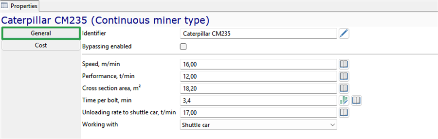
The following properties must be set for each continuous miner type:
-
Unique identifier
-
Bypassing enabled - if checked, the equipment unit of this type will participate in bypassing maneuvers when traveling along the arcs that require vehicle bypassing.
-
Speed, m/min - average moving speed of this type of roofbolters in m/min.
-
Performance of ore mass cutting in tons per minute
-
Cross section area, m2
-
Time per bolt, min duration of one bolt installation in minutes
-
Working with — is used to set whether continuous miners of this type work with shuttle cars or with conveyors.
-
Unloading rate to shattle car, t/min - rock mass unloading rate from the continuous miner into the shuttle car. This field is filled in when working with shuttle cars
On the tab Cost you can fill the cost of operating this type of equipment (but not necessarily).
Scaler type
A Scaler is a self-propelled unit used to remove loose rock and irregularities from the surface of a stope.

For each type of Scaler, the following key properties must be specified:
-
Unique identifier
-
Bypassing enabled - if checked, the equipment unit of this type will participate in bypassing maneuvers when traveling along the arcs that require vehicle bypassing.
-
Scaling performance, m2 per minute
-
Speed, km/h - average moving speed of this type of roofbolters in km/h.
On the tab Cost you can fill the cost of operating this type of equipment (but not necessarily).
Mobile equipment
The Mobile Equipment element of the object tree contains lists of all mobile equipment units defined in the scenario, organized by equipment type. It also includes a list of underground trains and railveyors, which — unlike other mobile equipment — are not grouped into types.
General parameters
Each equipment unit, except for trains and rail conveyors, is defined by the following key properties:
-
Unique identifier of the equipment unit
-
Included — indicates whether the equipment unit will be used during planning/simulation
-
Base node — the default location of the unit on the mine map (garage)
-
Idling policy — action after completing tasks:
-
Default — trucks and LHDs return to the garage; drill rigs and bolters remain in the stope
-
Return to base node — all equipment returns to the garage after completing work
-
Stay at current location — all equipment remains at the location where it finished its last task
-
-
Mine area or Mine areas to which the equipment unit is assigned
-
Availability, % — the average percentage of time the equipment is in operation. During planning/simulation, breaks are automatically generated so that the average availability of the equipment over the simulation period — before applying other downtime periods — matches the specified value
-
Initial fuel or charge level, % — the fuel level in the tank or charge level of the installed battery at the start of the simulation, expressed as a percentage of its full capacity
-
Equipment type — displayed as reference information in the equipment properties; its properties cannot be edited
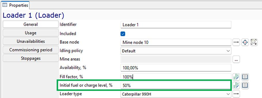
In addition to these main properties, there are equipment-specific properties applicable only to certain equipment types:
-
For trucks, LHDs, and shuttle cars — Fill factor, which allows modeling variability of equipment load (constant or stochastic)
-
For shuttle cars — Maximum haulage distance, in meters
-
For continuous miners — Buffer capacity in tonnes and Volum in m³
Usage
On the Usage tab, the initial state of parameters related to maintenance based on operating hours is specified for each mobile equipment unit:
-
Time, h — total time accumulated by the equipment unit since its last maintenance at the start of planning/simulation
-
Working time, h — number of engine hours (hours of engine operation during travel, loading, unloading) accumulated by the equipment unit since its last maintenance at the start of planning/simulation
-
Distance, km— number of kilometres travelled by the equipment unit since its last maintenance at the start of planning/simulation
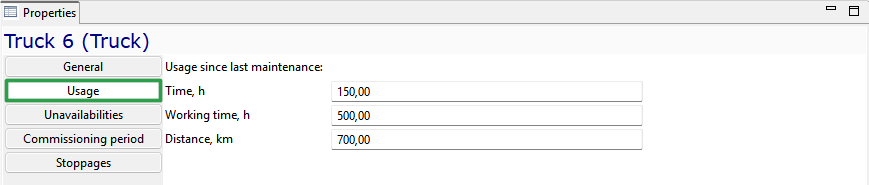
Unavailabilities
On the Unavailabilities tab, scheduled periods of unavailability can be specified for each equipment unit.
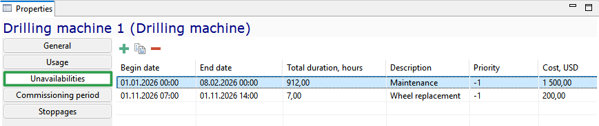
The  buttons allow you to add, copy, and delete unavailability periods.
Commissioning period
On the Commissioning period tab, the commissioning and decommissioning dates of an equipment unit may be specified, as well as the costs associated with commissioning (purchase) and decommissioning (disposal). Prior to the commissioning date / after the decommissioning date, the equipment unit does not participate in planning/simulation.
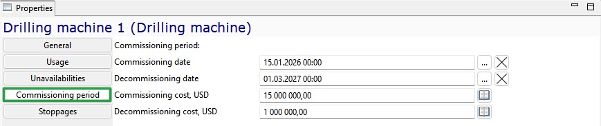
Stoppages
On the Stoppages tab, all downtime events (maintenance, scheduled downtime periods, unplanned events) assigned to the equipment unit in the Schedules object tree group are displayed.
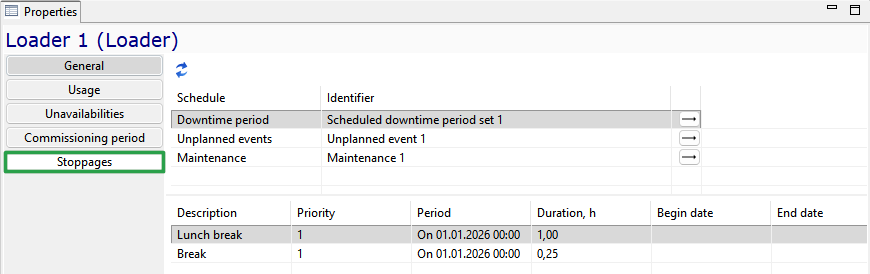
The  button allows you to refresh the list of schedules, and the
  button allows you to navigate to the selected schedule for editing.
Train
Train - a transport unit in the form of a separate train that consists of several rail cars, designed to transport ore mass on the rails. Unlike other mobile equipment, trains are not grouped into types.
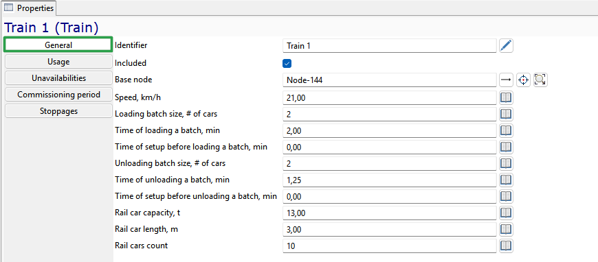
The following basic parameters are set for a train:
-
Unique identifier
-
Included - parameter that indicates whether the equipment unit will be used for scheduling/simulation
-
Base node - base location (depo)
-
Speed, km/h
-
Loading batch size, number of cars - how may rail cars can be loaded simultaneously
-
Time of loading a batch, min - loading duration, min
-
Time of setup before loading a batch, min - delay before loading can start
-
Unloading batch size, number of cars - how may rail cars can be unloaded simultaneously
-
Time of unloading a batch, min - unloading duration, min
-
Time of setup before unloading a batch, min - delay before unloading can start
-
Rail car capacity, t - capacity of one rail car in metric tons
-
Rail car length, m - Length of one rail car in meters
-
Rail cars count - number of rail cars in the train.
Schedules
The Schedules model tree element contains the following entities that regulate the work of the mine:
-
Shifts
-
Blast periods
-
Schedule downtime period sets
-
Maintenance sets
-
Unplanned events.
Shifts
Shifts are used to simulate the operation of equipment following the work schedule. Shifts determine the periods when equipment is available for operation.
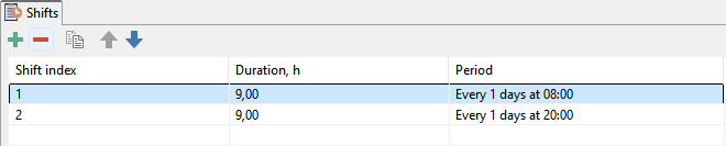
The following parameters are set for each shift:
-
Shift index - an optional field to indicate a shift
-
Duration of shift, in hours
-
Period - the period of the shift can be specified as an exact time or as a recurrence pattern (every n-th day of the month, every last day of the month, every week, every n days).
Shifts in the Shifts model tree group are common to all mobile equipment units and applied during scheduling and simulation only to them.
Blast periods
Blast periods define the time intervals when the formation of broken-up ore mass is simulated in all blocks in selected mine areas that are ready for blasting at the start of the blast period.
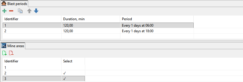
The Blast period has following parameters:
-
Unique identifier of the blast period
-
Duration of the blast period in minutes
-
Period of the blast period, which can be specified as an exact time or as a recurrence pattern (every n-th day of the month, every last day of the month, every week, every n days)
-
Mine areas where the above blasting operations are carried out.
The Blast periods model tree element contains a list of all blast periods that can be assigned to the mine areas during scheduling and simulation.
Scheduled downtime period sets
Scheduled downtime period sets are used to model planned periods of equipment unavailability within a fixed time interval, regardless of the equipment’s operating time, engine hours, or mileage. In this way, this period sets can represent lunch breaks, routine shift maintenance (RSM), major repairs, or equipment upgrades.
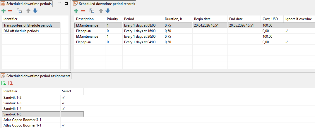
Three types of entities are created in MineTwin OpenPit to set up Scheduled downtime period sets:
-
Scheduled downtime periods in the upper-left window, each possibly containing several individual Scheduled downtime period records
-
Scheduled downtime period record — a row of data describing a single downtime in the upper-right Scheduled downtime period records window. A downtime record is defined by the following parameters:
-
Description — an optional description of the scheduled downtime period
-
Priority — an index defining the position in the hierarchy of unavailability periods. Periods with a smaller value of the index (higher priority) overwrite periods with higher value (lower priority). Lower priority unavailability periods will not be scheduled if they occur during periods with higher priority.
-
Duration, h — the length of the planned downtime period, in hours
-
Begin and end dates — specified if the downtime occurs only during a limited time frame, e.g., winter months. If left blank, the downtime applies throughout the entire scenario.
-
Cost, USD — the expenses associated with carrying out this downtime type, e.g., routine shift maintenance (RSM) cost
-
Ignore if overdue — if checked, this parameter allows to ignore the downtime if its time interval has already passed. For example, a truck has a scheduled lunch break from 13:00 to 14:00, but it is still waiting to be loaded by an excavator that is on break. In this case, the truck effectively experiences a break during that wait, so there is no need to simulate an additional one-hour break once the truck completes its trip after the excavator returns.
-
-
Scheduled downtime period assignments window at the bottom allows you to assign Scheduled downtime periods to selected equipment units.
The buttons allows you to select all equipment units / clear all selections.
Maintenances
Maintenance sets are used to simulate scheduled equipment repairs — those carried out after a specified calendar time of operation, upon reaching a defined number of engine/impact mechanism hours, or upon reaching a specified mileage. In this way, different types of maintenance can be defined, such as routine maintenance, intermediate repairs, major overhauls, etc.
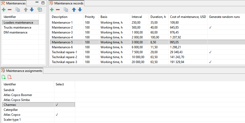
Three types of entities are created in MineTwin OpenPit to set up Maintenance sets:
-
Maintenances in the upper-left Maintenances window, each possibly containing several individual Maintenance records
-
Maintenance record — a row of data describing a single maintenance/repair in the upper-right Maintenance records window. A maintenance is defined by the following parameters:
-
Description — an optional description of the maintenance/repair
-
Priority — an index defining the position in the hierarchy of unavailability periods. Periods with a smaller value of the index (higher priority) overwrite periods with higher value (lower priority). Lower priority unavailability periods will not be scheduled if they occur during periods with higher priority.
-
Basis — the type of maintenance trigger: calendar time, engine operating hours, or equipment mileage.
-
Interval — the interval between two maintenance triggers, expressed either in hours or kilometers, depending on the chosen basis.
-
Duration, h — the duration of the maintenance
-
Cost, USD — the expenses associated with the maintenance (optional)
-
Generate random runs — if checked, maintenance for all equipment units without a defined initial operating time will not be simulated simultaneously. Instead, maintenance triggers will occur at different randomly assigned times for each unit.
-
-
Maintenance assignments window at the bottom allows you to assign Maintenances to selected equipment types.
The buttons allows you to select all equipment types / clear all selections.
Unplanned events
Unplanned events are used to simulate emergency equipment failures, breakdowns, or downtime caused by weather conditions.
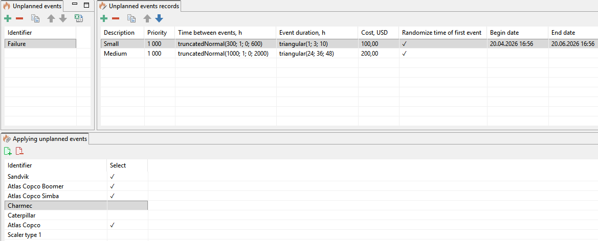
To define Unplanned events in MineTwin OpenPit, three types of entities are created:
-
Unplanned events in the upper-left Unplanned events window, each possibly containing several individual Unplanned events records
-
Unplanned events record — a row of data describing a single Unplanned event in the upper-right Unplanned events records window. Such event is defined by the following parameters:
-
Description — an optional description of the event
-
Priority — an index defining the position in the hierarchy of unavailability periods. Periods with a smaller value of the index (higher priority) overwrite periods with higher value (lower priority). Lower priority unavailability periods will not be scheduled if they occur during periods with higher priority.
-
Time between events, h — may be specified as a constant or as a random variable using one of the built-in distributions.
-
Event duration, h — may be specified as a constant or as a random variable using one of the built-in distributions.
-
Cost, USD — the expenses associated with the event (optional)
-
Randomize time of first event — used so that equipment failures are not simulated simultaneously for all units; instead, the countdown starts at different randomly assigned times for each unit
-
Begin and end dates — specified if the events occur only during a limited time frame, e.g., winter months. If left blank, the events will happen throughout the entire scenario.
-
-
Unplanned events assignments window at the bottom allows you to assign Unplanned events to selected equipment types.
The buttons allows you to select all equipment types / clear all selections.
Note: Scheduled downtime periods are assigned to Equipment units and most Material flow elements, while Maintenances and Unplanned events are assigned to Equipment types and Conveyers.
Hierarchy of Unavailability Periods
For each equipment unit, different types of unavailability periods can be defined:
-
Blasting periods, scheduled downtime periods, maintenance, and unplanned events (via schedules)
-
Commissioning/decommissioning and unavailability (in equipment properties)
During planning/simulation, these periods may overlap in time. Priorities are used to regulate overlapping periods.
Breaks with a lower priority index are higher priority and override (absorb) breaks with a higher index (lower priority). By default:
-
Unavailability periods and out-of-service periods have the highest priority = -1
-
Scheduled downtime periods = 1
-
Maintenance = 100
-
Unplanned events = 1000
This means that if a major repair (priority -1) coincides with a daily lunch break (priority 1), the lunch break will not be scheduled. If a failure (priority 1000) occurs during current maintenance (priority 100), that failure will not be considered in the simulation.
If necessary, the user can adjust the priorities of unavailability periods.
Plans
MineTwin Underground can automatically form an equipment operation plan based on target plans for mining ore mass or stopes.
Stopes plan
The stopes plan specifies how much ore mass and what quality must be mined in each period in each stope.
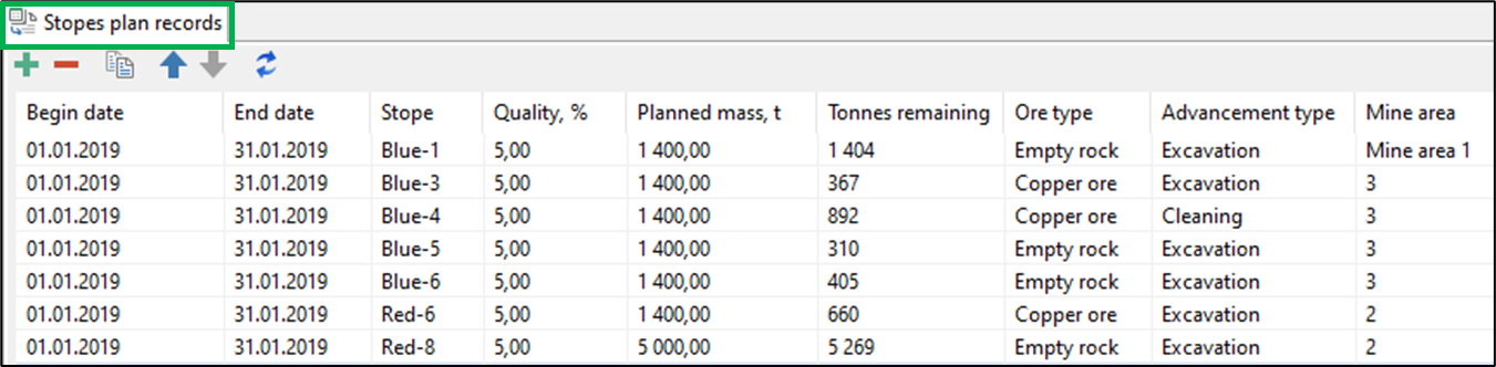
Each stopes plan record is characterized by the following parameters:
-
Begin and end dates of the planning period
-
Stope
-
Quality of the mined ore mass
-
Planned mass, t.
-
Remaining mass, t – quantity of remaining ore mass in stopes
-
Ore type
-
Advancement type
-
Mine area.
