Define equipment units and run simulation
In this section, we will proceed with the scenario developed in the previous step. Ensure that this scenario is currently active in MineTwin before moving forward.
We will now focus on expanding this scenario by adding equipment units. After we define the equipment units, we will do the final adjustments to the scenario. And run the first simulation experiment.
1. Define equipment units and their base locations
In an earlier stage of developing our scenario, we established various equipment types. Now, it’s time to create the individual equipment units. In MineTwin, the process of creating equipment units is more straightforward than creating types, since most of the equipment characteristics are already defined at the equipment type level.
We want to set the home locations of the equipment pieces to this part of the map, the little square with road ROAD-13, ROAD-14 and ROAD-15.

To add a truck, do the following actions:
-
In the scenario tree view, navigate to Trucks item, that can be found under the Equipment units section.
-
In the Trucks list view in the bottom middle part of the screen, click the + button to add a truck
-
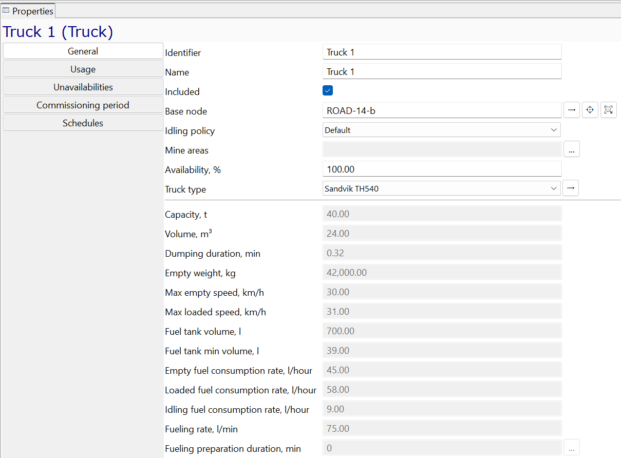
In the truck’s Properties view select a type of the truck
-
In the same truck’s Properties view select its base node using the Select from 2D editor button:

Here is how the Properties view of our newly created truck should look:
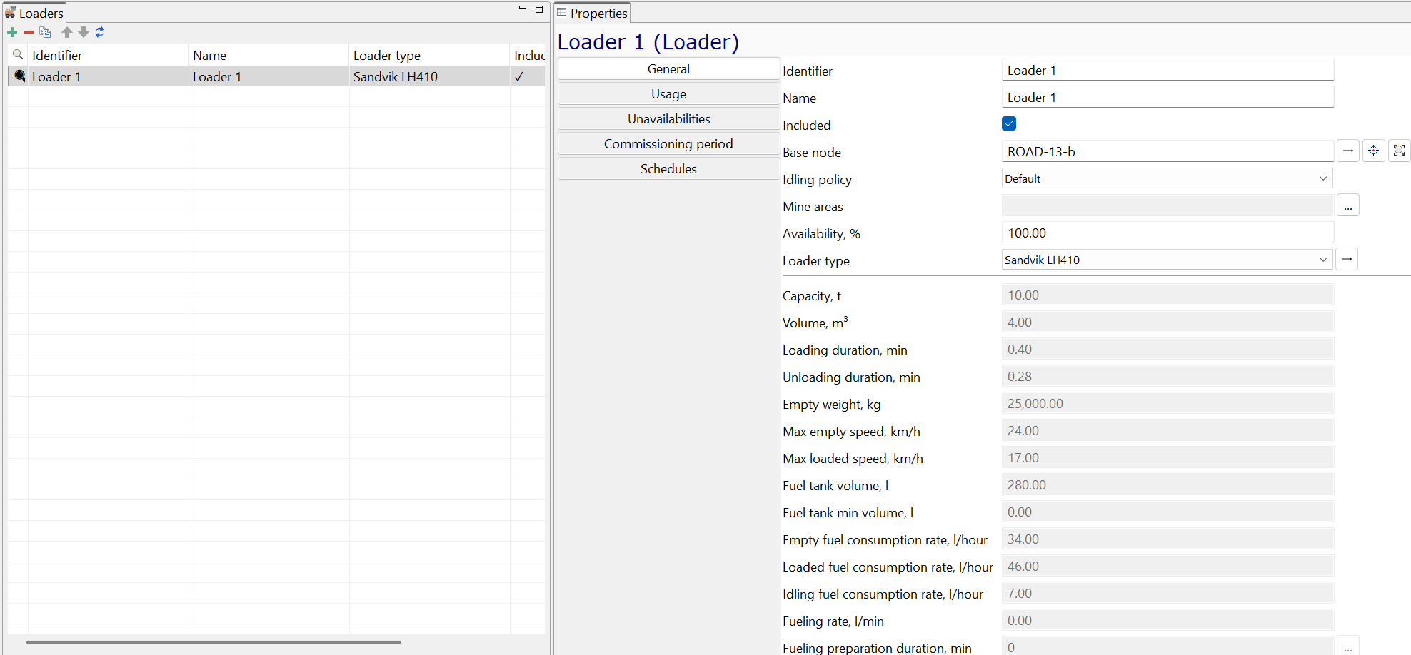
Similar to the truck, let us now add a loader to our scenario and place it to a node in the same place of our mine:
Here is how the Properties view of the newly created loader should look:
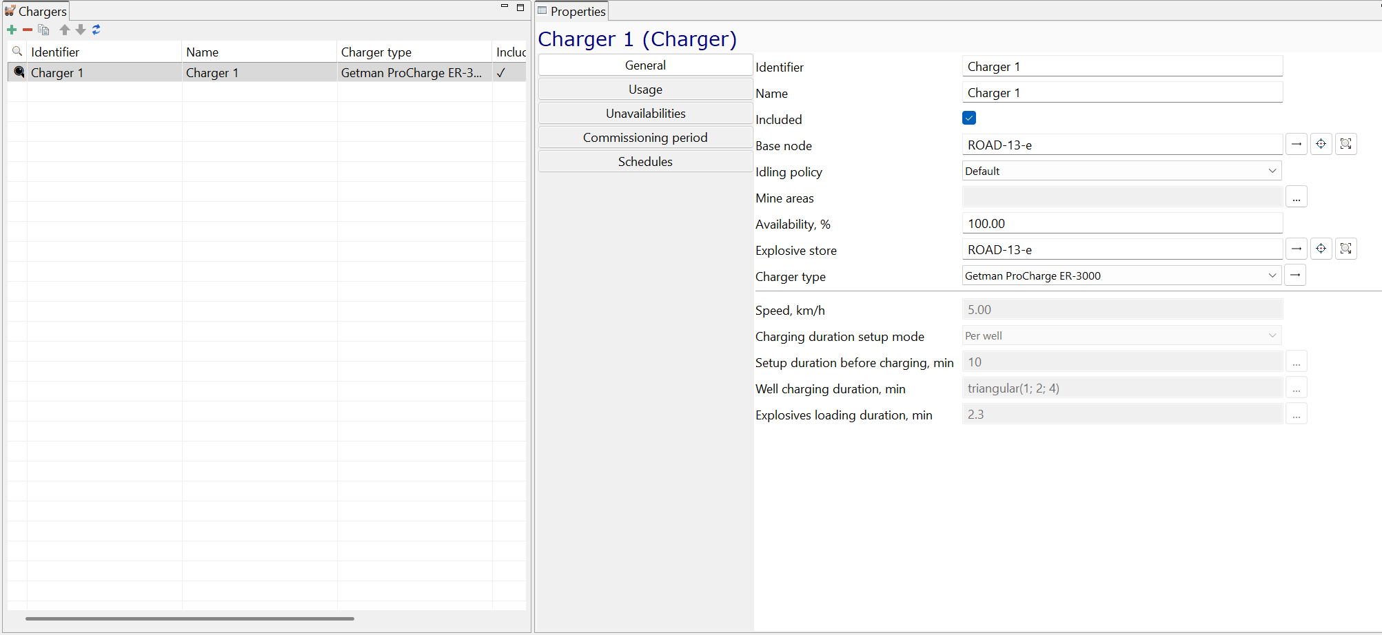
Let us continue adding equipment units by creating a charger. The process of creating a charger is very similar to the one of creating a loader or a truck, the only difference is that you also need to set the location of the Explosive store, i.e. the location of where the charger goes to get explosives.
The result of creating a charger can look like this:
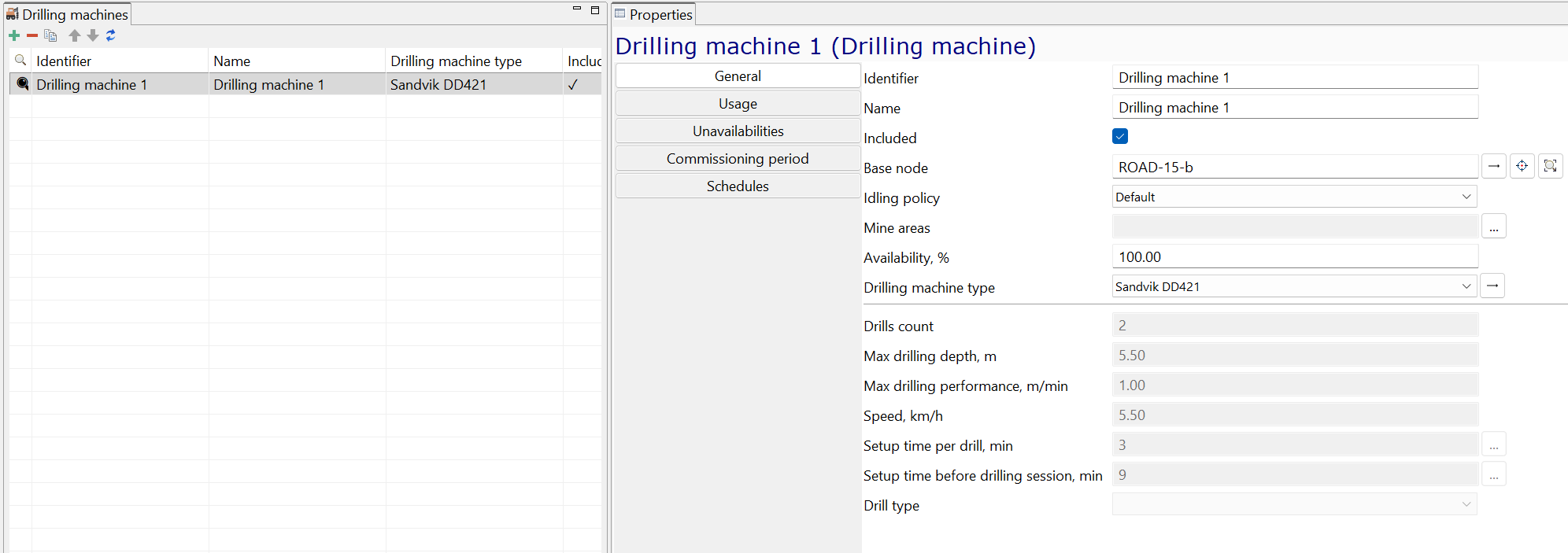
The last equipment unit we need to add is a drilling machine. The process is fully analogous to adding a charger, and the result is shown in the screenshot below:
So, now we have created 4 equipment units. Note how they are shown in the scenario tree view:

2. Fix the equipment inconsistencies
Are all the equipment types and equipment units sufficient for simulating the mining method we have selected? To check this, let us now hit the Check button and see if there are any errors and warnings:
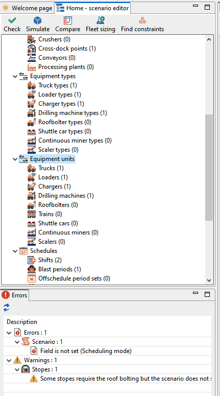
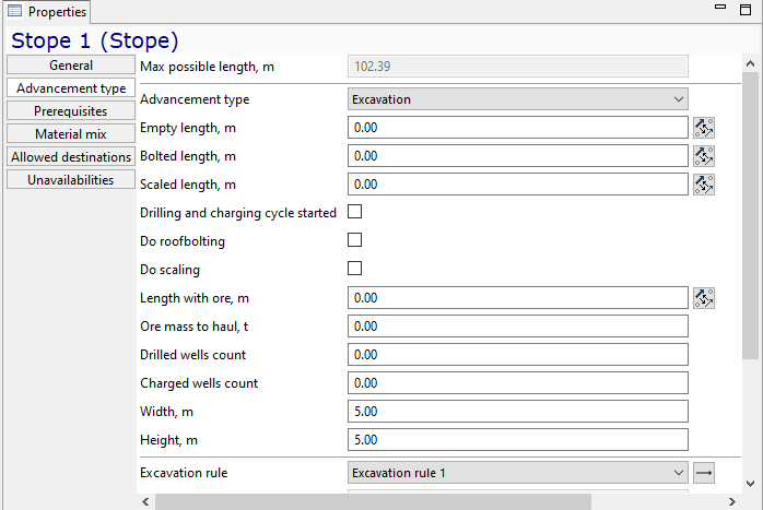
The first error tells that our stope requires roof bolting, but there are no roof bolter in the scenario. This can be fixed by disabling the roof bolting for our stope for now. To do this:
-
Select the Stopes item in the scenario tree view
-
Go to Advancement type section of stope’s Properties view
-
Uncheck Do roofbolting check box
3. Fix the scheduling mode and set the production target
Let’s now turn our attention to the warning message displayed. It states, 'Scenario has scheduling mode By tasks, but no tasks are defined. Either change the scheduling mode or add some tasks for the equipment.'
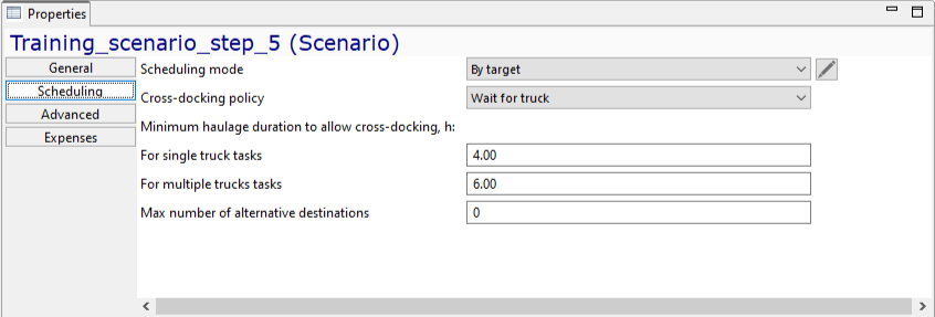
The scheduling mode is a crucial element that drives the MineTwin simulation. The default mode, By tasks, requires users to set a precise working schedule for each piece of equipment. However, this approach is not suitable for our current tutorial. Instead, we want MineTwin to utilize its built-in scheduler, enabling it to automatically assign tasks to all equipment to meet a specified production target.
This can be implemented by setting the scheduling mode to By target in the Properties page of the scenario:
Now, we need to define that target. To do so, click on the Target plan tree item at the very bottom of the scenario tree view under the Plan section. Then, set the following record to the target plan table. Set the target quality to 5% and the planned mass to 10,000 tons::
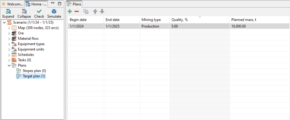
Note: The format of the date is dependent on your local machine settings and might look different compared to the screenshot above.
4. Run the first simulation
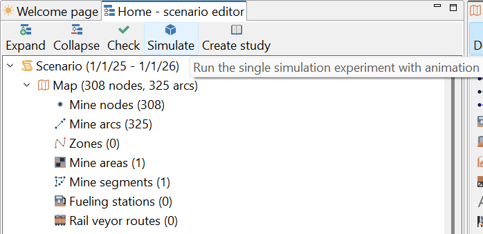
Now we have created the first version of scenario that can be run in simulation mode! Let us click the simulate button and see what happens:
MineTwin with a switch to a single simulation run mode. The simulation can be started by clicking the Run button in the application toolbar:
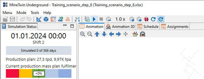
Let us adjust the simulation view to enjoy seeing how our mining process is being simulated:

You can zoom in and out of charts by simply clicking on them and scrolling with your mouse. You can also navigate around the simulation view by activating different tabs, filtering, selecting and de-selecting enabled items.
Now that we have a running simulation, we can save it and continue with the next step. The resulting scenario can be downloaded here.