Create a scenario from scratch
1. Use new scenario wizard
In this section, we start building a new MineTwin OpenPit scenario from scratch using the scenario wizard. We will walk through the initial configuration together and show how the general scenario settings, ore types, and shift calendar are defined before any geometry, equipment, or production logic is added.
These initial settings create the foundation for the rest of the guided training, where we will gradually turn an empty scenario into a working simulation model.
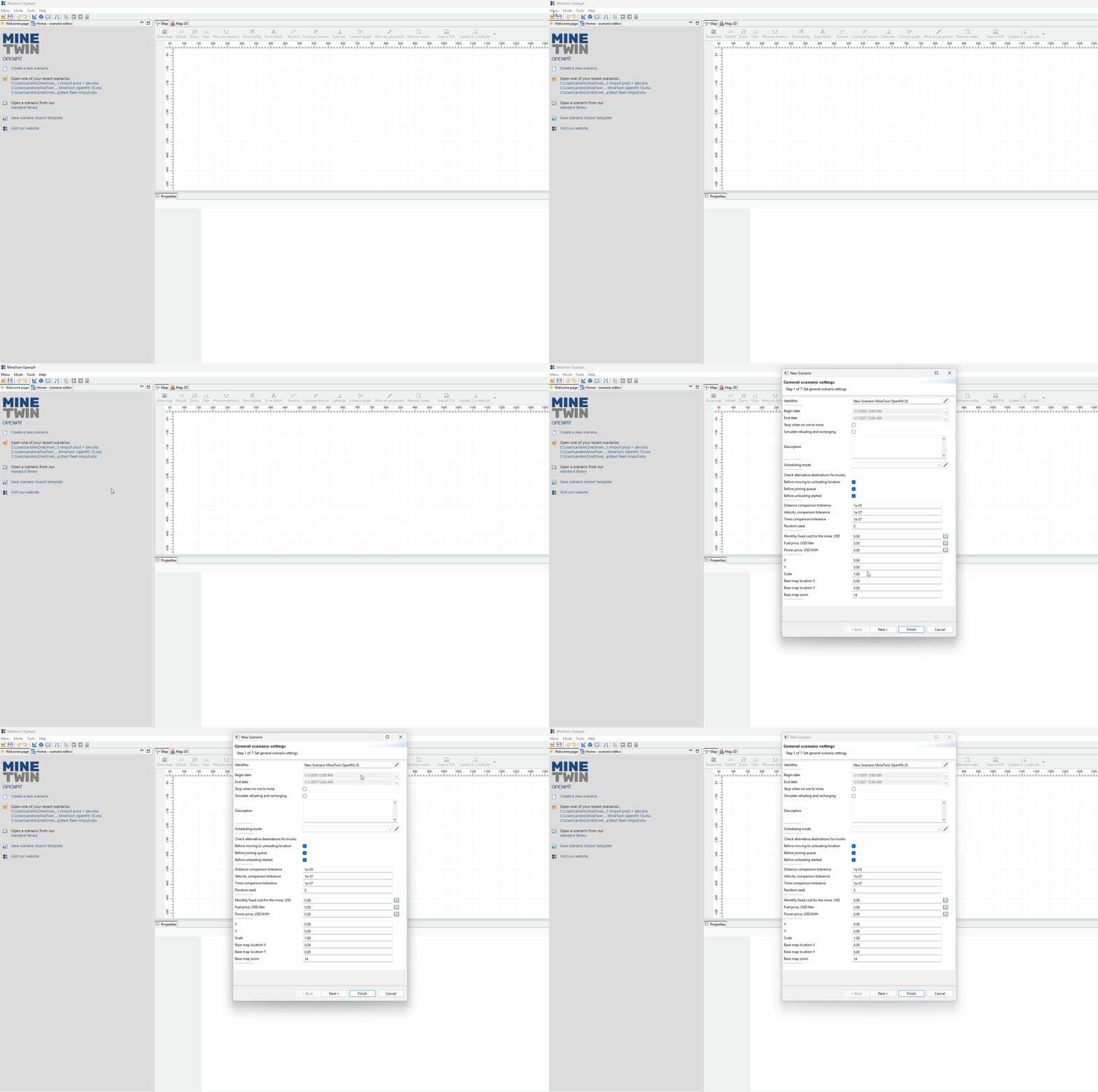
We begin by opening the new scenario wizard. This wizard guides us through the required setup steps and helps ensure that the scenario has the minimum configuration needed before we continue with modeling.
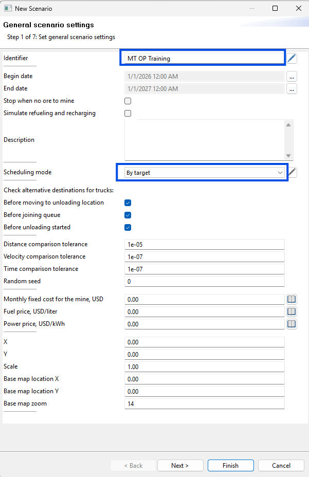
Here we define the general scenario settings: the scenario name and the planning method. These settings identify the scenario and determine how we will approach planning before we continue with the rest of the model setup.
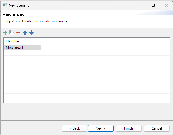
At this step, we add a single mine area to the scenario. In MineTwin OpenPit, a mine area is used to logically group adjacent mining blocks and can later help organize where specific equipment or transport units operate.
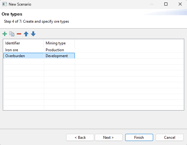
We configure two ore types: iron ore and overburden. MineTwin uses ore types during scheduling and to determine where material from blocks can be hauled, so this step prepares the scenario for later block setup and material flow configuration.
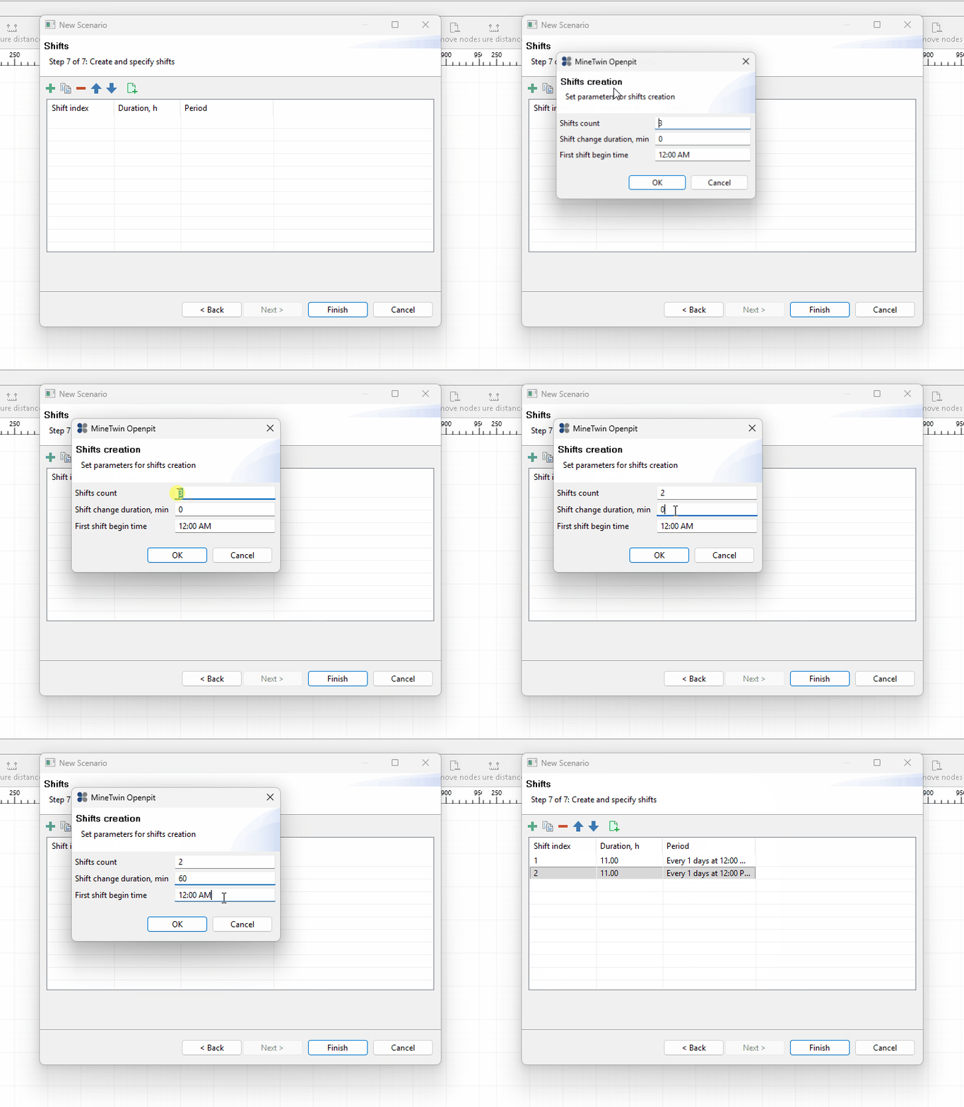
Finally, we configure two shifts for the scenario calendar. Shifts define the periods when mobile equipment is available for operation, and this schedule will be used later during planning, simulation, and result analysis.
2. Draw simple geometry and add text labels
In this section, we will create a simple schematic layout for the scenario. We will add text labels, draw the main road line with mine nodes and arcs, check the scenario for configuration issues, and add the first material destination object.
We will also prepare the geometry for later simulation by setting elevation values, reviewing the model in 3D, and adjusting virtual arc lengths. At the end of this section, we will run an empty simulation to confirm that the base scenario can be executed before we add excavation blocks and equipment.
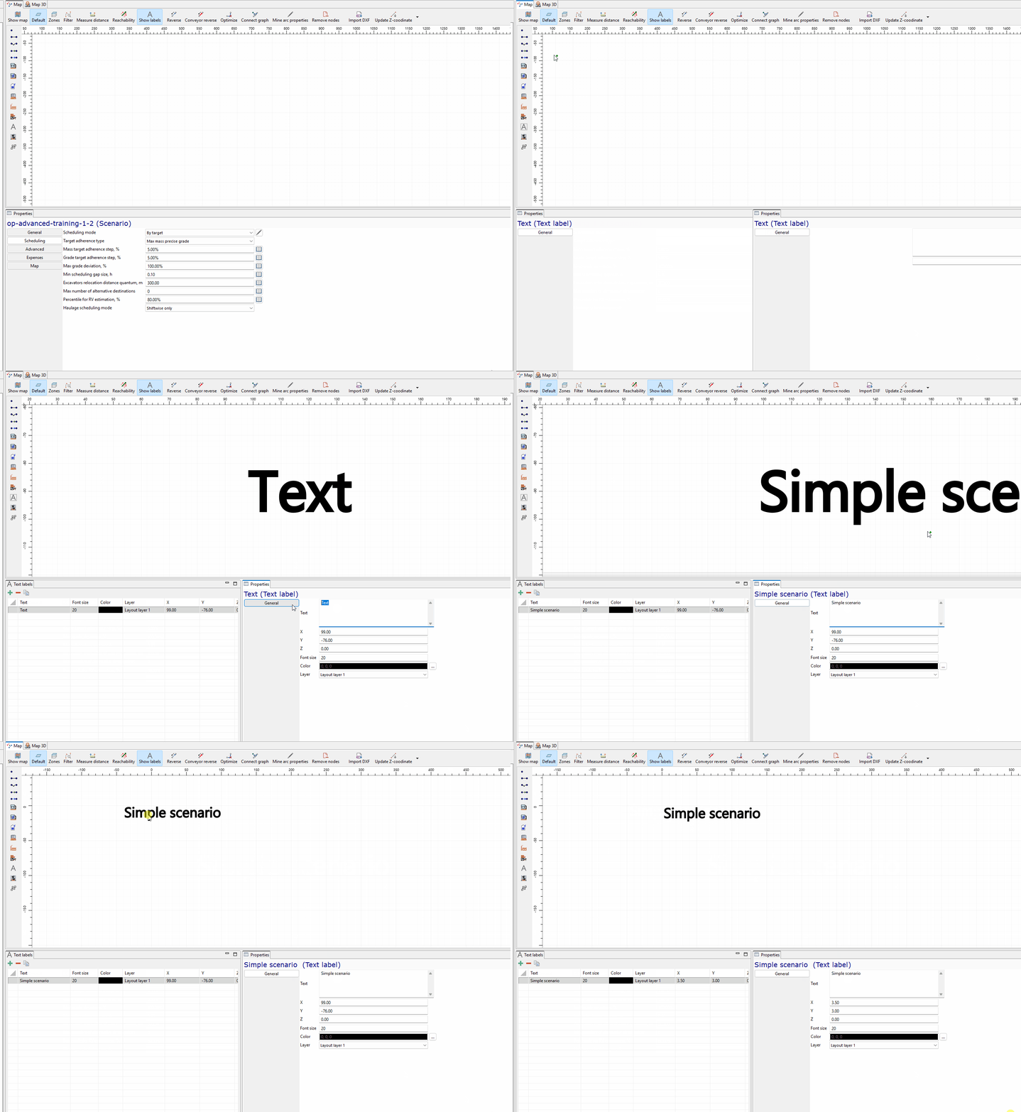
We start by adding a text label with the scenario title. This label helps make the model easier to read during the guided demonstration and gives the scenario canvas a clear visual reference.
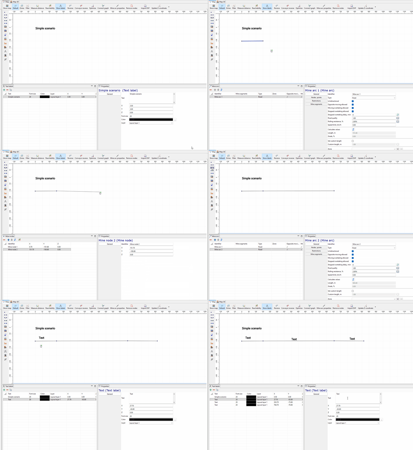
Next, we draw a simplified road geometry for the training scenario and place labels for the main areas. The layout represents the future excavation block, the in-pit road, and the off-pit road as a simple connected network of mine nodes and arcs.
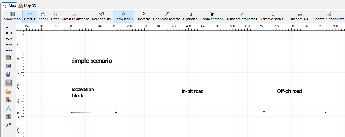
We then update the labels shown on the map for the Excavation block, In-pit road, and Off-pit road. These labels make the simplified layout easier to read during the next configuration steps.
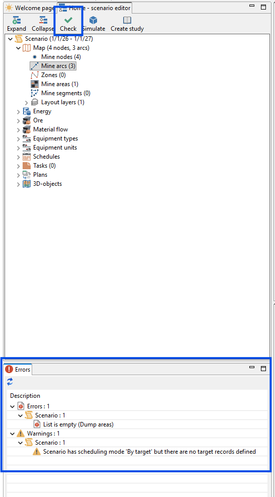
After creating the initial geometry, we check the scenario for errors. At this stage, MineTwin reports that the dump area list is still empty and shows a warning that the scenario uses the By target planning mode but has no target records yet. We will address these items in the following steps by adding a dump area and then defining the production target later in the training.
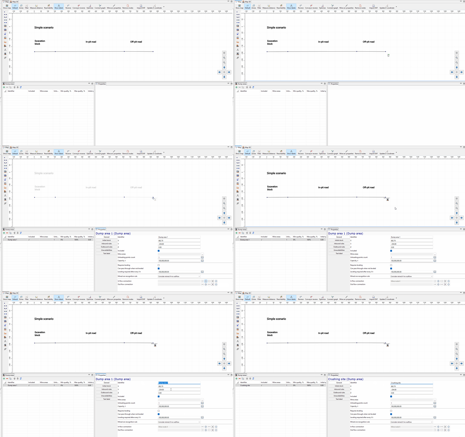
We add a dump area at the end of the road network and name it Crushing site. In MineTwin OpenPit, dump areas act as haulage destinations for material from blocks, so this step prepares the scenario for material movement once excavation blocks and equipment are configured.
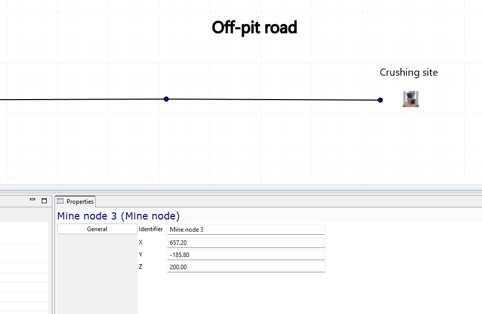
At this step, we set elevation values for the mine nodes. The screenshot shows the Z coordinate being edited for a mine node. MineTwin uses these node elevation values to calculate road grades for the connected arcs.
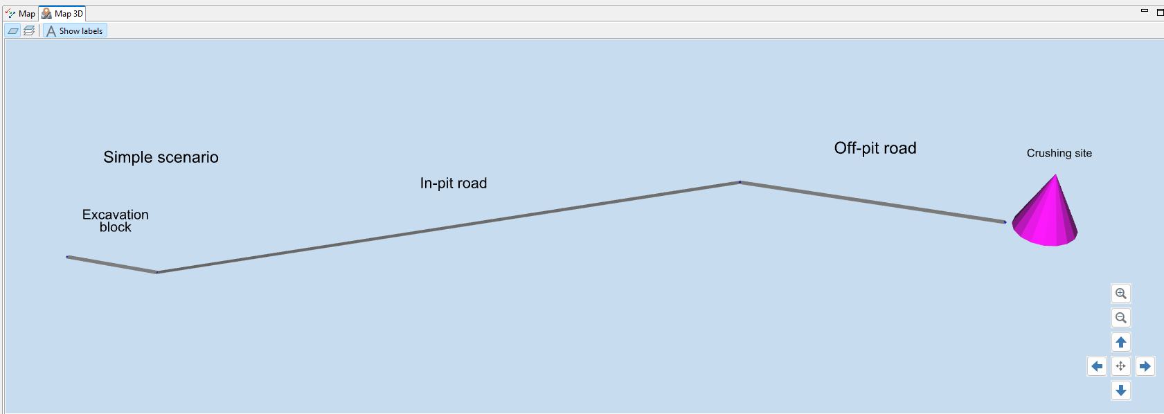
We review the scenario in the 3D view to confirm that the road profile, labels, and Crushing site are displayed as expected. This visual check helps us verify that the node elevations created the intended vertical profile before simulation objects are added.
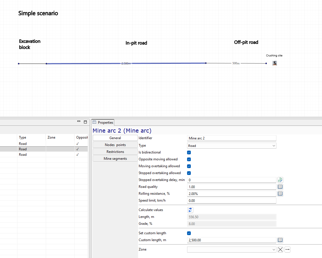
We set custom virtual lengths for the road arcs, including a 2,500 m in-pit road section and a 500 m off-pit road section. This allows the simplified schematic geometry to represent realistic haulage distances without drawing every road segment at full scale.
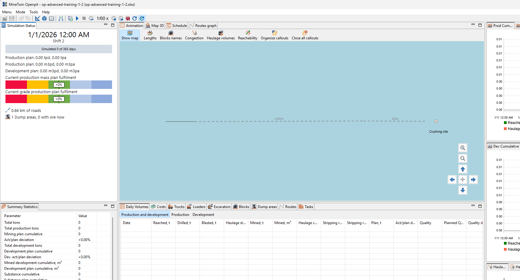
Finally, we run the scenario without excavation blocks or equipment. The simulation view shows the basic road network and one dump area, while production and development values remain zero. This confirms that the base scenario can run and is ready for the next stage of the training.
3. Add excavation block, ore, and set target
In this section, we will turn the schematic road layout into the first mineable part of the scenario. We will create a mine segment, add a block that corresponds to this segment, and define the block properties needed for planning and simulation.
We will also configure the block advancement logic, material mix, scenario duration, and target plan. By the end of this section, MineTwin will know where material can be mined from, what material is inside the block, and what production target we want to reach during the planning period.
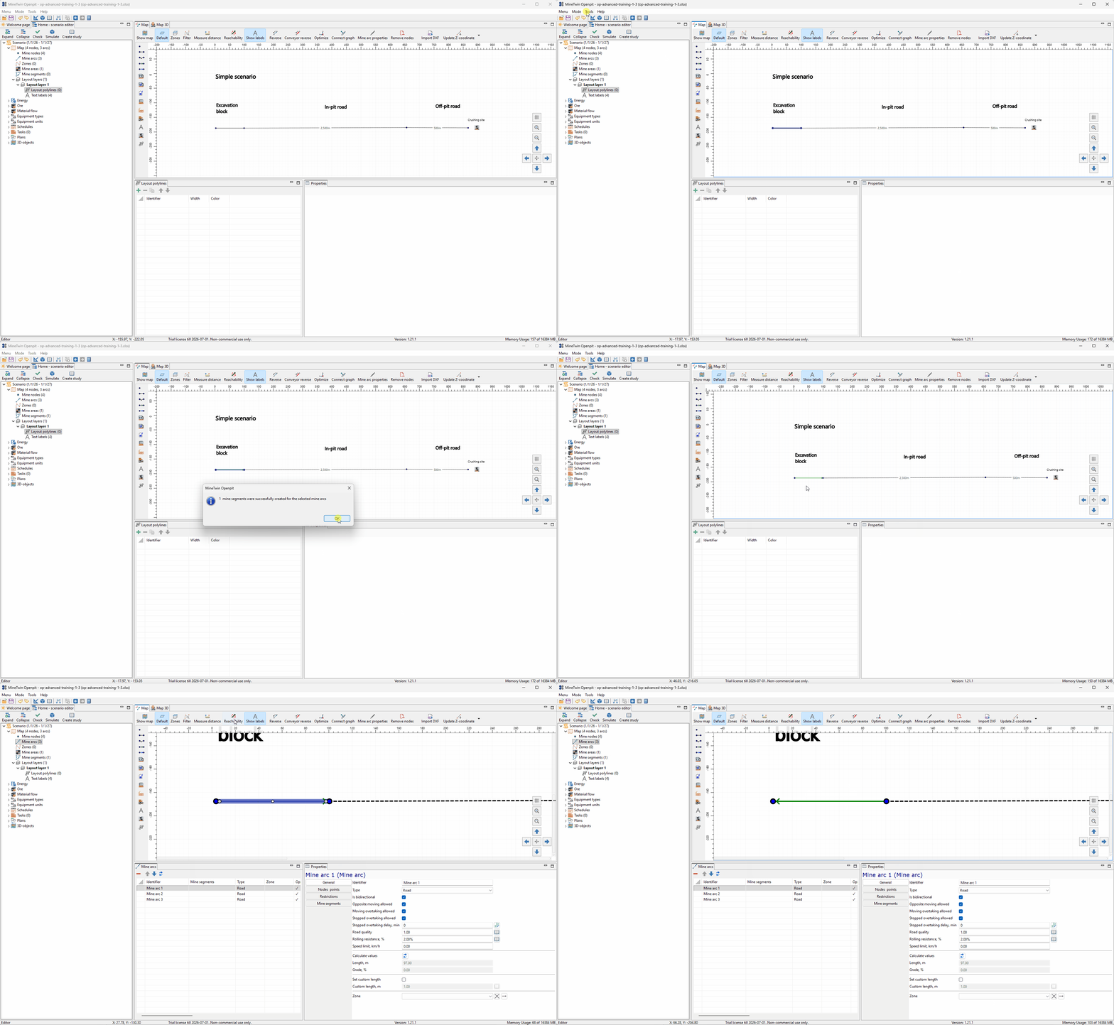
We start by creating a mine segment on the road network and setting its direction. The mine segment represents the location on the plan where the future block will be mined, so its position and direction define how the block is connected to the haulage layout.
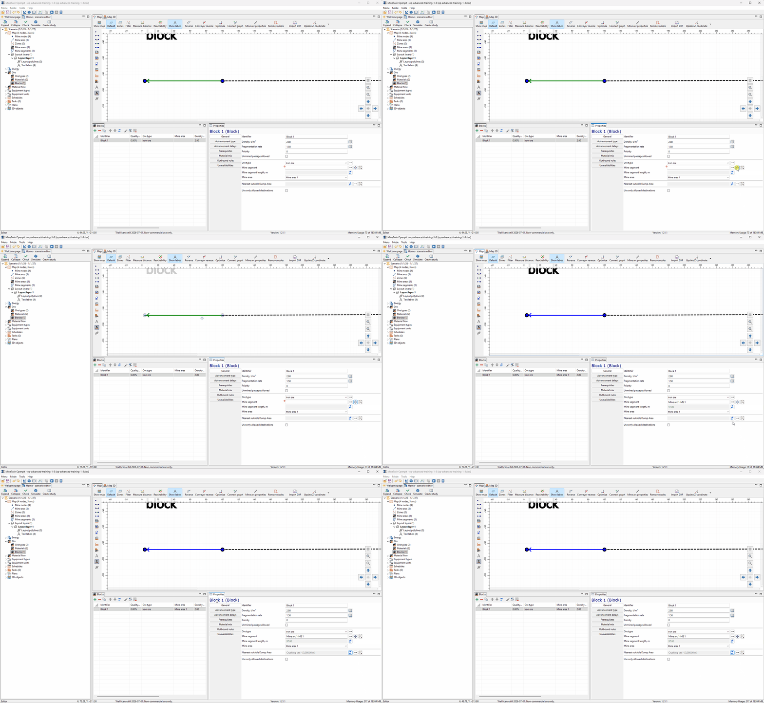
Next, we add a block and associate it with the mine segment. In MineTwin OpenPit, a block is the place where equipment performs mining operations, and on the mine plan it corresponds to a mine segment.
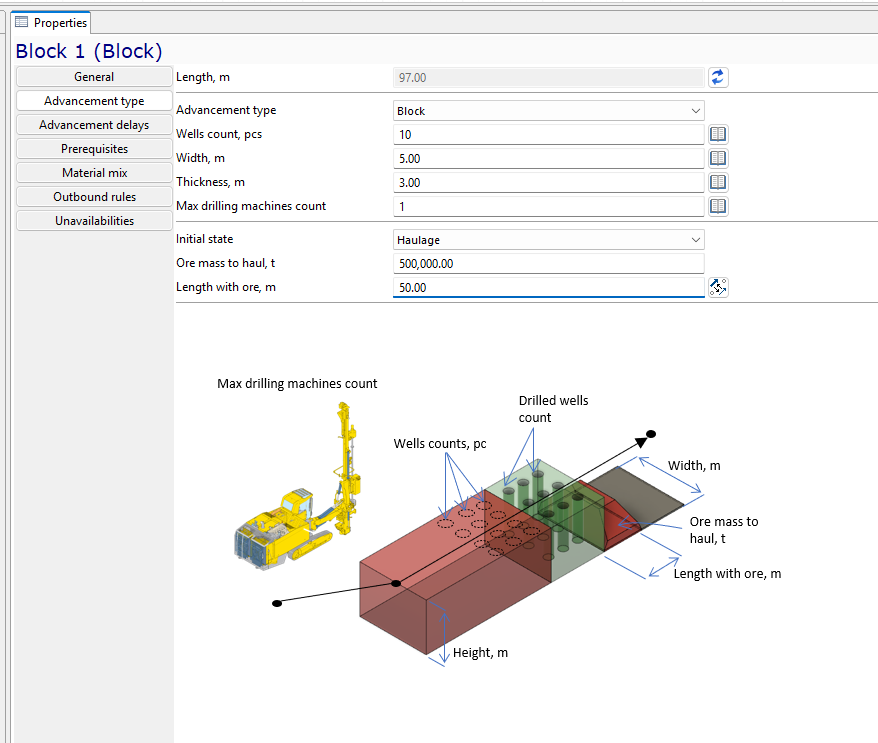
We configure the block advancement type as Block and set the initial state to Haulage. In this training scenario, the block already contains ore mass ready to be hauled, so we specify the ore mass to haul and the length of the block where this ore is located.
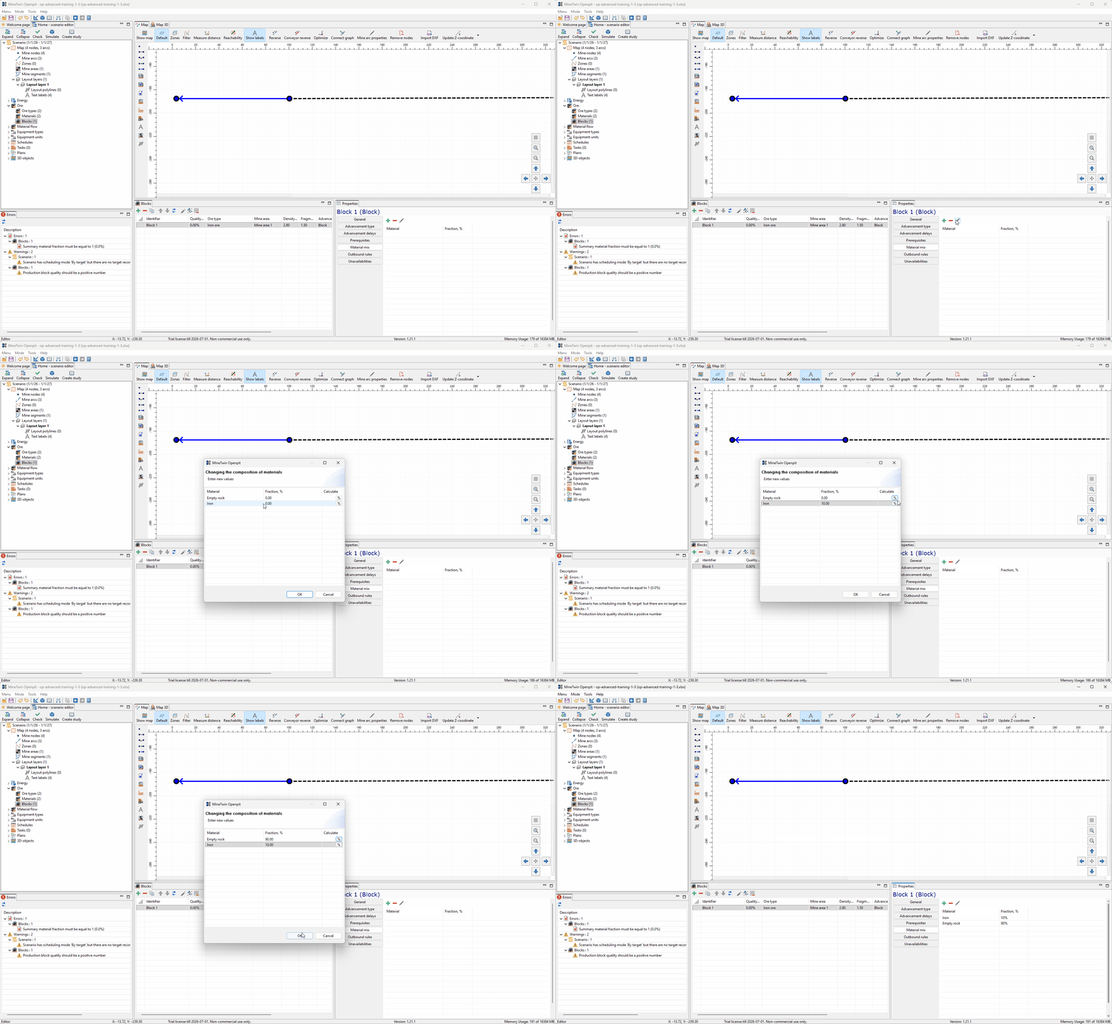
We fill in the block material mix. This step is required because MineTwin uses the material composition to calculate the block quality; the material fractions must add up to 100% before the block can be used correctly in planning and simulation.
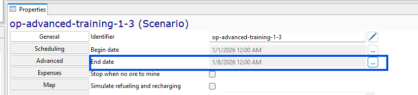
We adjust the scenario end date so the planning period lasts one week, from January 1, 2026 to January 8, 2026. This gives the model a clear time horizon for the first target-based planning run.

Finally, we add a target plan record for the same one-week period. The target specifies Production mining type, 10% quality, and 500,000 t of planned mass, which tells MineTwin what production result we want the scenario to achieve.
4. Add trucks, excavators, and run simulation
In this section, we will complete the minimum working configuration for the scenario by adding mobile equipment. We will first define the equipment types, then create actual truck and excavator units that can be used by the simulation.
After the equipment is added, we will run the first working simulation. This lets us confirm that the block, material destination, road network, target plan, and equipment are connected well enough for MineTwin to execute the mining and haulage process.
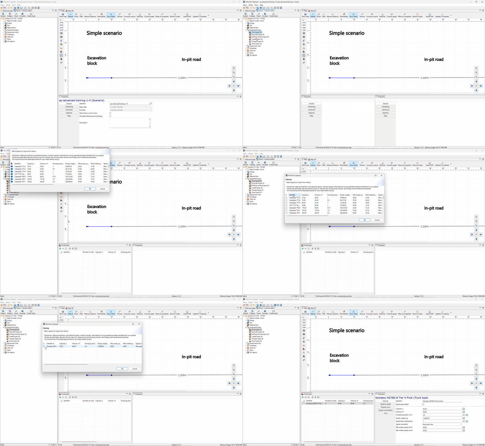
We start by adding a truck type from the MineTwin truck models library. In this example, we use the Komatsu HD785-8 Tier 4 Final model. Its parameters are populated from the library, but they can still be edited in the scenario, including payload capacity, body volume, dumping duration, and loaded and empty travel speeds.
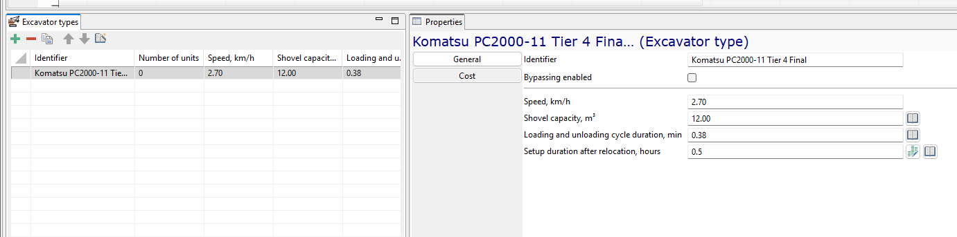
Next, we add an excavator type for the loading operation. The screenshot shows the Komatsu PC2000-11 Tier 4 Final model. Its parameters are also populated from the library and can be adjusted if needed, including shovel capacity and loading cycle duration.
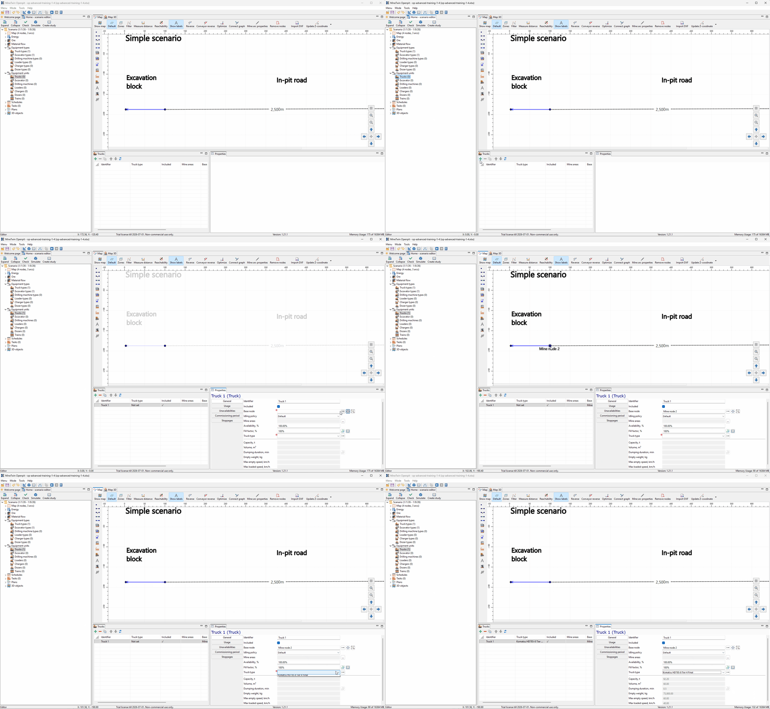
We create a truck unit based on the selected truck type and assign it to a base node. The base node defines the truck’s initial position at the start of the simulation.
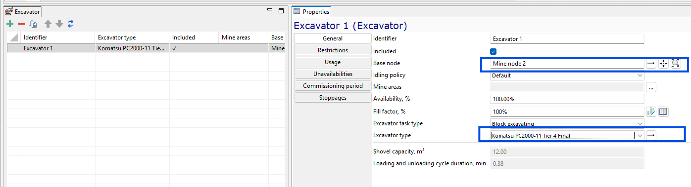
We create an excavator unit based on the selected excavator type and assign it to a base node as its initial position. The excavator task type is set to Block excavating, which means this excavator will load ore from the excavation block rather than perform dump area load-out.
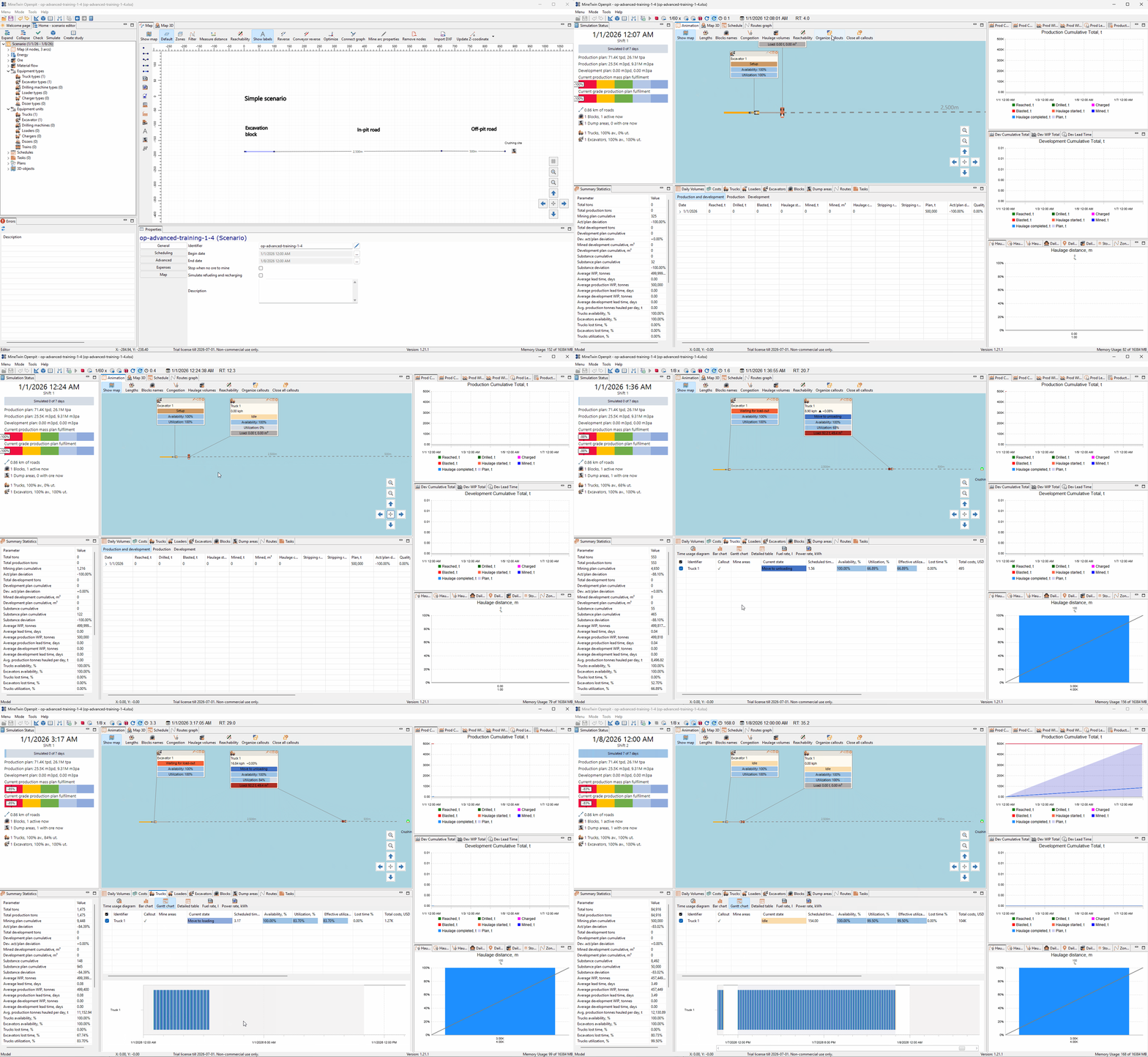
Finally, we run the first working simulation. As the simulation starts, MineTwin opens the simulation view and shows callouts for the excavator and truck on the map. The excavator goes through setup and load-out states, while the truck cycles through loading, moving to unloading, unloading, and returning for the next load. During the run, the status panel, daily volumes table, production cumulative chart, haulage distance chart, and truck Gantt chart are updated. By the end of the one-week period, the scenario has mined and hauled material, but the production result is still below the 500,000 t target, giving us a baseline for later analysis and improvement.