Add battery-electric equipment
In this section, we convert the selected underground equipment to battery-electric operation. We keep the same material flow and equipment assignment logic from the previous section, then add battery types, a recharging bay, and power consumption parameters.
The goal is to see how recharging changes the scenario performance. After the first run with batteries, we will review whether the existing fleet can still meet the corrected plan or whether recharging creates a new operational constraint.
1. Add batteries and recharging
In this section, we enable recharging simulation and add the minimum energy infrastructure needed for the battery-electric run. We use swappable batteries for both LHDs and trucks, so equipment can replace a depleted battery and the removed battery can recharge at the bay.
We begin with one recharging bay at the depot and a limited number of simultaneous charging places. This makes the first electric-equipment run useful for training, because the charging process can become visible in the schedule instead of being hidden by oversized infrastructure.
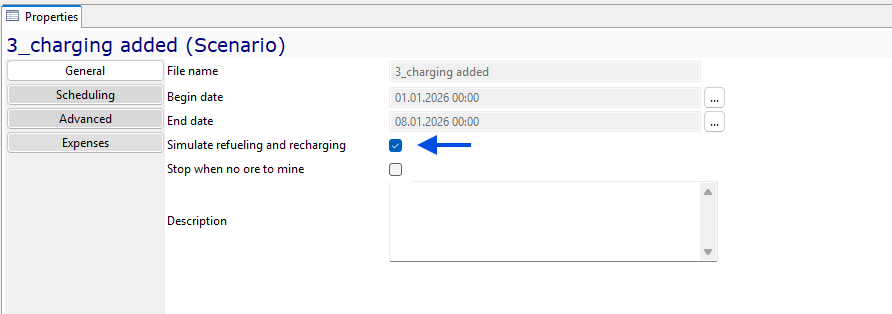
We open the scenario advanced settings and enable Simulate refueling and recharging. This tells MineTwin to include battery state, recharging tasks, and possible waiting for charging infrastructure in the simulation.
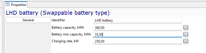
We create the swappable battery type for the LHD fleet. For the LHD battery, we set capacity to 360 kWh, minimum capacity to 55 kWh, and charging rate to 250 kW.
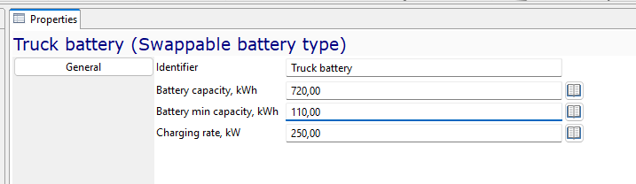
We create a separate swappable battery type for the truck fleet. For the Truck battery, we set capacity to 720 kWh, minimum capacity to 110 kWh, and the same charging rate of 250 kW. The charging rate is the same because both battery types use the same charging infrastructure.
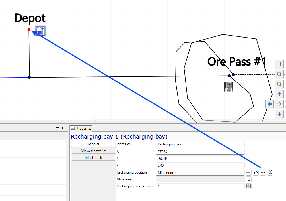
We add Recharging bay 1 at the depot and assign its recharging position to the depot node. For the first run, we keep the recharging places count at 1. This means only one battery can be charged at a time, so the bay can become a constraint when several machines need batteries.
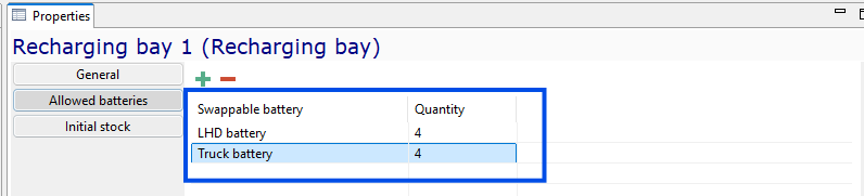
We define the allowed batteries and initial stock for the recharging bay. We add 4 LHD battery units and 4 Truck battery units. This gives the scenario spare batteries for swapping, while still requiring the charging bay to recover depleted batteries over time.
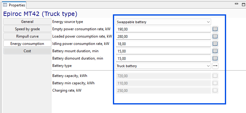
We open the Epiroc MT42 truck type and set its energy source type to Swappable battery. We set empty movement power consumption to 190 kW, loaded movement power consumption to 280 kW, and idling power consumption to 18 kW. We also set battery mount and dismount duration to 15 minutes and select Truck battery as the battery type.
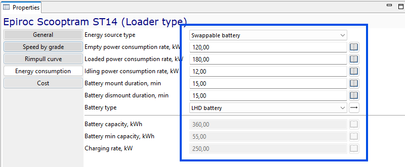
We open the Epiroc Scooptram ST14 loader type and set its energy source type to Swappable battery. We set empty movement power consumption to 120 kW, loaded movement power consumption to 180 kW, and idling power consumption to 12 kW. We also set battery mount and dismount duration to 15 minutes and select LHD battery as the battery type.
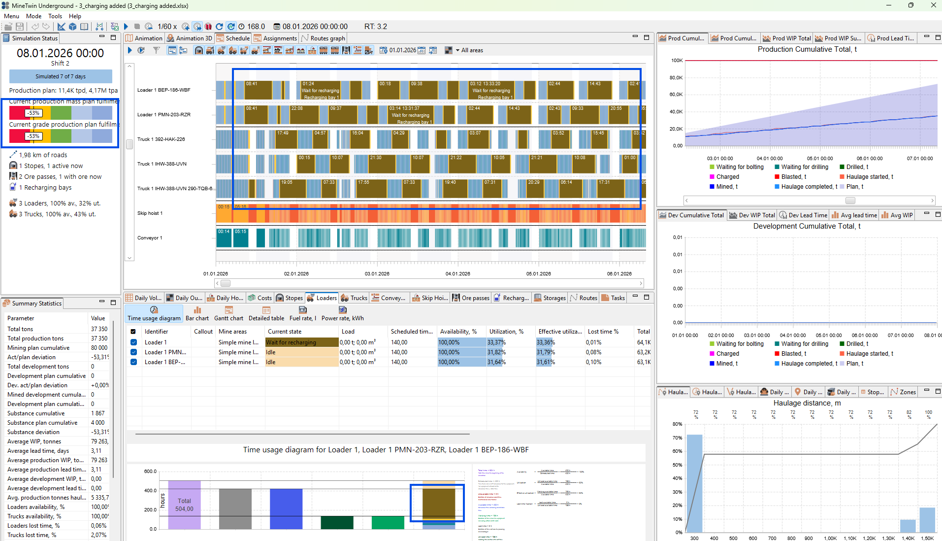
We run the scenario after adding the batteries, recharging bay, and energy consumption parameters. The schedule now shows long periods of waiting for recharging. The production status shows that the plan is no longer fulfilled, because too much operating time is lost while equipment waits for battery charging. This gives us the next problem to solve: the electric fleet needs enough charging capacity and spare batteries to support the same production target.
2. Vary the number of recharging places
In this section, we start looking for the charging infrastructure capacity needed to recover the production plan. The first battery-electric run showed that one recharging place creates too much waiting for recharging.
We will run a variation study for the number of recharging places in the recharging bay. This lets us test whether increasing charging capacity is enough to remove the new bottleneck before changing the equipment fleet.
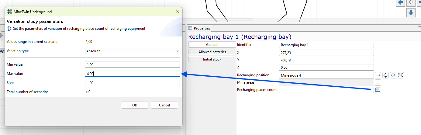
We create a variation for Recharging places count in Recharging bay 1. We use an absolute range from 1 to 4 with a step of 1. MineTwin will generate four scenarios, so we can compare how the plan fulfillment changes when the bay can charge more batteries at the same time.

We review the completed variation study results. Increasing the number of recharging places from 1 to 2 and then to 3 improves the production result. However, increasing the number from 3 to 4 does not improve plan fulfillment. The equipment utilization indicators also remain effectively unchanged between the 3-place and 4-place scenarios. This tells us that adding a fourth charging place is not useful for this scenario.
We save the generated scenario with 3 recharging places. This keeps the smallest charging bay configuration that gives the best result in this variation study.
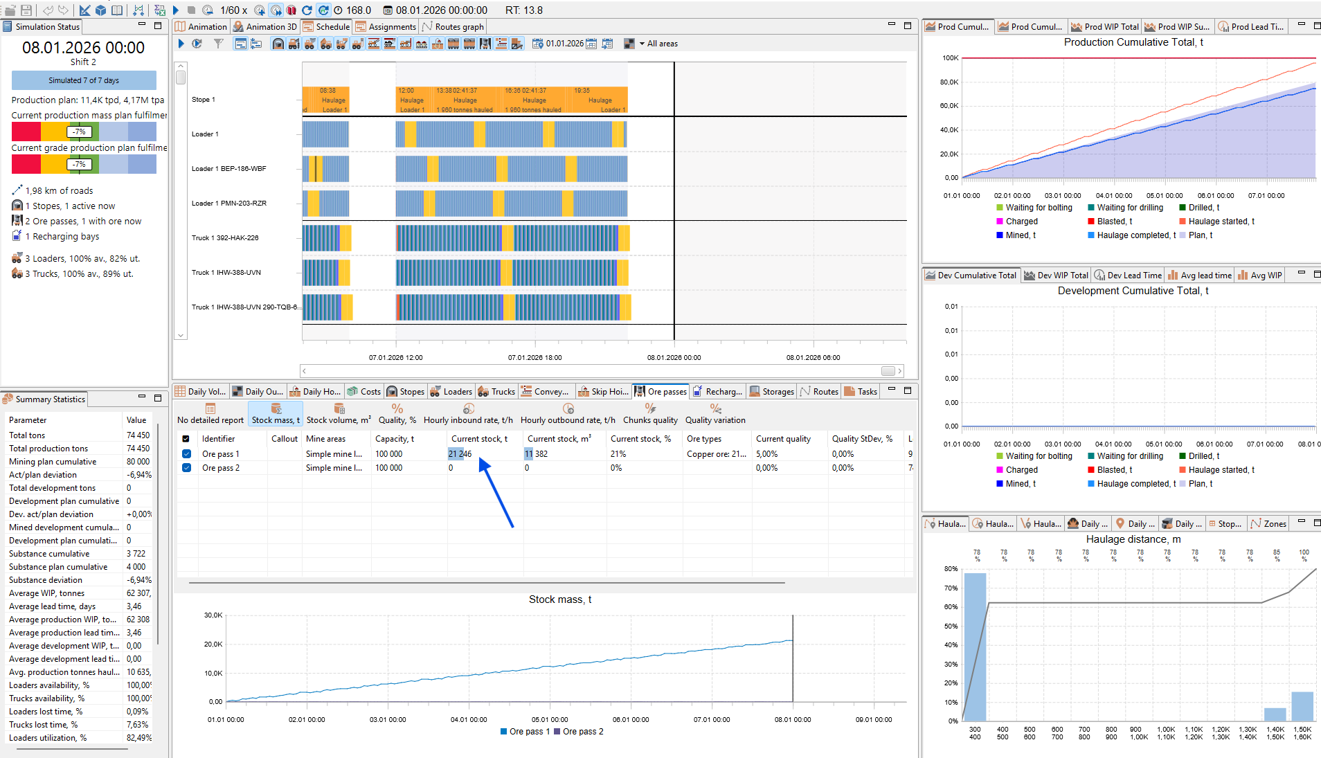
We run the saved scenario with 3 recharging places and look for the next bottleneck. The ore pass table shows that material is accumulating in Ore pass 1, while Ore pass 2 does not accumulate stock. This means the truck haulage leg between the two ore passes cannot move material away from Ore pass 1 fast enough.
This result is expected after adding battery-electric operation. The trucks must climb the ramp to reach the recharging bay, change batteries, and then return down the ramp before continuing haulage. Those extra trips reduce the effective capacity of the second haulage leg.

We run fleet sizing again from the scenario with 3 recharging places. This time, MineTwin compensates for the additional truck travel to the recharging bay by adding trucks. The selected candidate keeps 3 LHDs and increases the truck fleet to 5 Epiroc MT42 trucks. This scenario fulfills the corrected production target, so we save it for further analysis. At the same time, the effective truck utilization is still not high. The added trucks help the plan, but they also spend a noticeable share of time waiting in the loading queue under Ore pass 1.